Advanced Weather v1.4 in Flightgear 2.6+

Part I: Convective clouds

Author: Thorsten Renk

The screenshots shown in the following use shaders, textures and scenery which are for various reasons (incompatible license, too recent development,…) not part of the official Flightgear 2.6 release. However, these are available for download and every feature works with Flightgear 2.6. The following packages need to be installed in addition to get to see the same: lightfield shader package v1.1, Juneau custom scenery, and textures from regional textures v0.1.

An integrated weather system

Without a doubt, clouds, haze and fog are the most easily noticed features of weather in a flight simulation, followed by winds. Advanced Weather v1.4 is however more than a tool to draw clouds and set wind parameters – it is a system with a (limited) understanding what the weather which it currently tries to render is, and it aims to simulate features of atmospheric physics.

This means that different weather phenomena tie together – winds and terrain influence the way cloud formation is taking place, cloud formation and the formation of thermal updrafts is connected, and weather is always understood as part of a large-scale weather pattern involving high and low pressure systems.

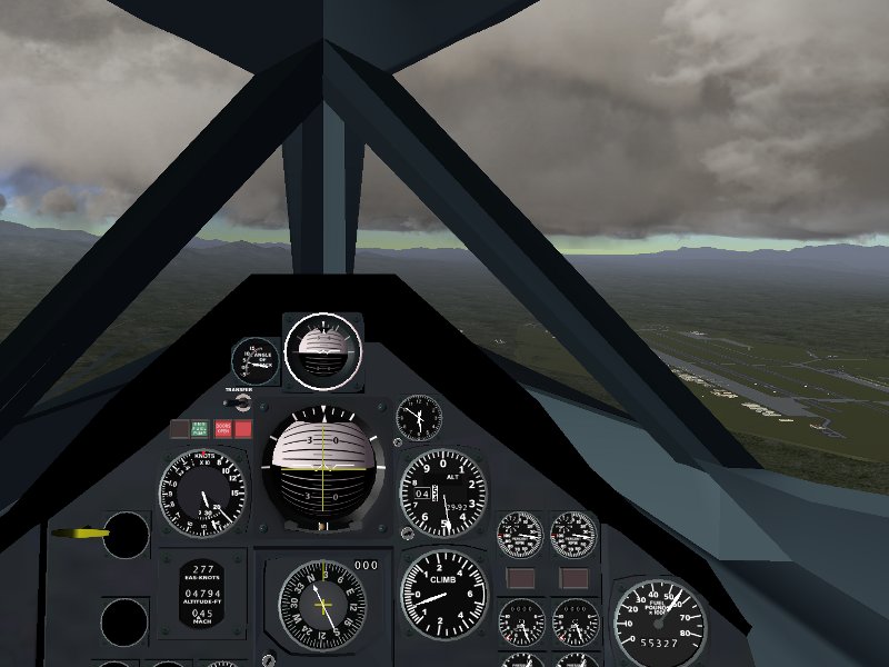
At the same time, clouds and atmospheric haze also influence the atmospheric light (and now also the scenery) in an essential way – strong fogging changes the color of sunrises to a blue-grey, wave patterns on the ocean follow the wind strength and direction and rain causes visibly wet runways. Let us have a look at how this works in fair weather.

The formation of convective clouds

Fair weather is typically characterized by convective cloud development: The sun heats the terrain and the air layer just above, thus warm air rises up in ‘bubbles’ and forms thermals, as the air rises, it expands and cools and eventually the moisture condenses into droplets, forming the characteristic, cauliflower-shaped Cumulus clouds. Cumulus clouds are the most common example of clouds formed by pronounced vertical motion of air.

As every glider pilot looking for thermals has to learn quickly, the formation of convective clouds depends on many different factors. The terrain type is crucial – while rock or concrete surfaces heat well in sunshine and may easily lead to well-developed thermals and cloud formation, open water or ice is much less likely to heat up in sunshine and seed Cumulus formation. High points in the terrain mark the spots where the bubbles of warm air are most likely to lift off the ground. Another important factor is the time of the day: The sun needs sufficient time to heat the terrain, therefore Cumulus formation is densest around noon, but the thermal updrafts are strongest in the afternoon, and while pronounced Cumulus clouds are unlikely to form in the morning, the thermal energy accumulated over a day may still give rise to well-developed clouds in the evening.

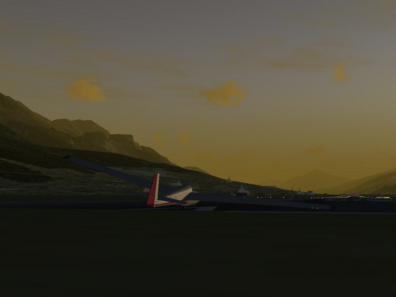
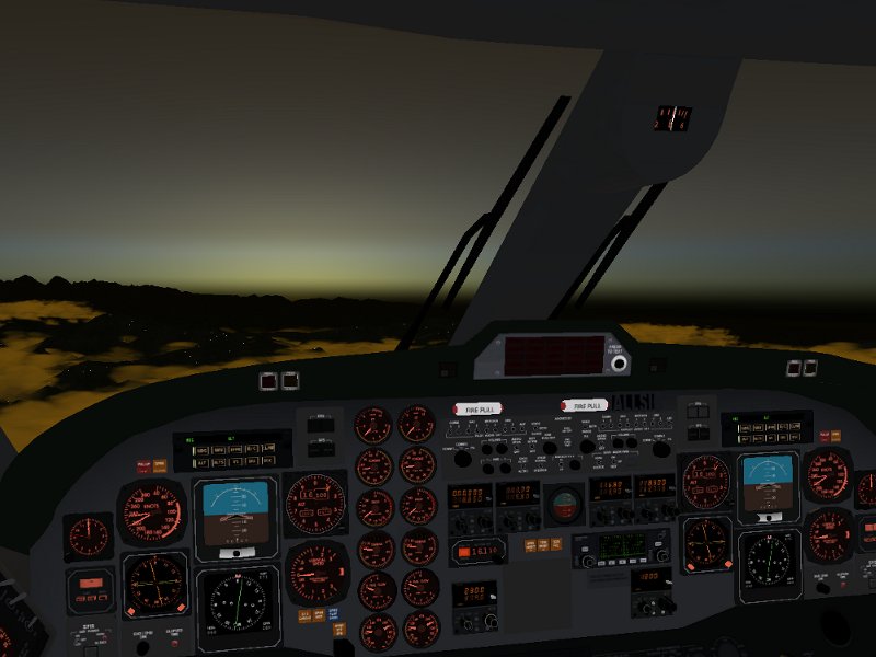
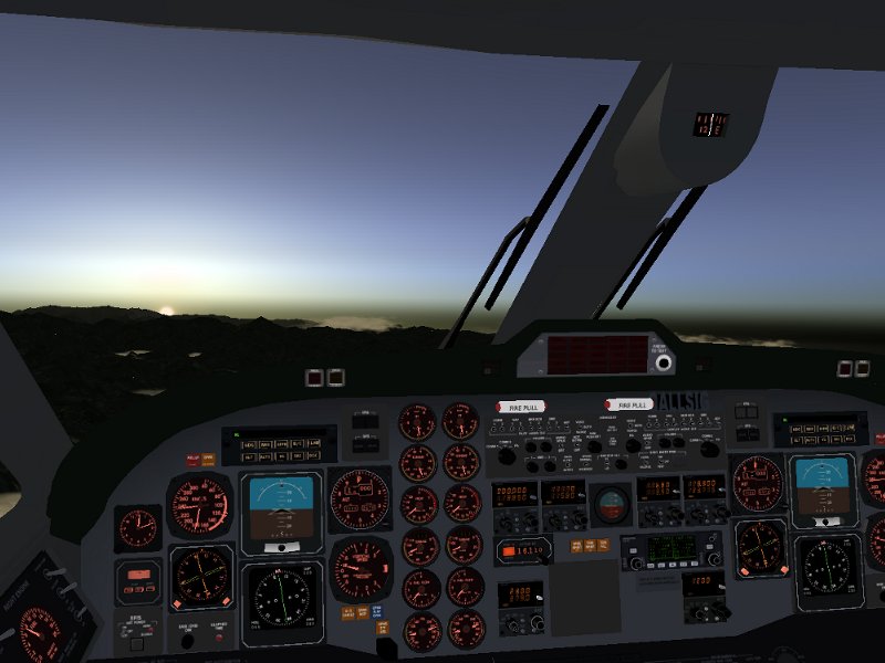
Let’s follow the development of convective clouds during a day in Juneau (Alaska). At sunrise, only very few clouds form, and they are transient, whispy phenomena (click to enlarge images):

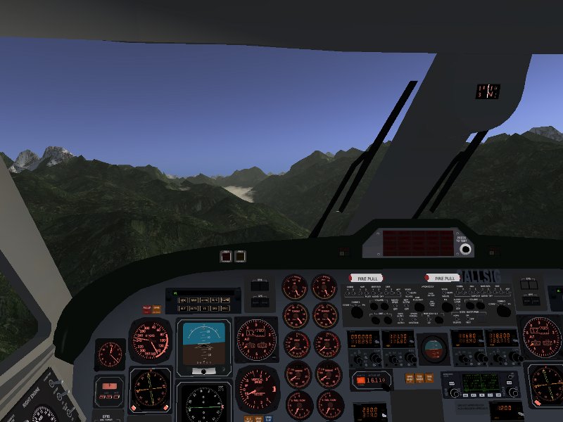
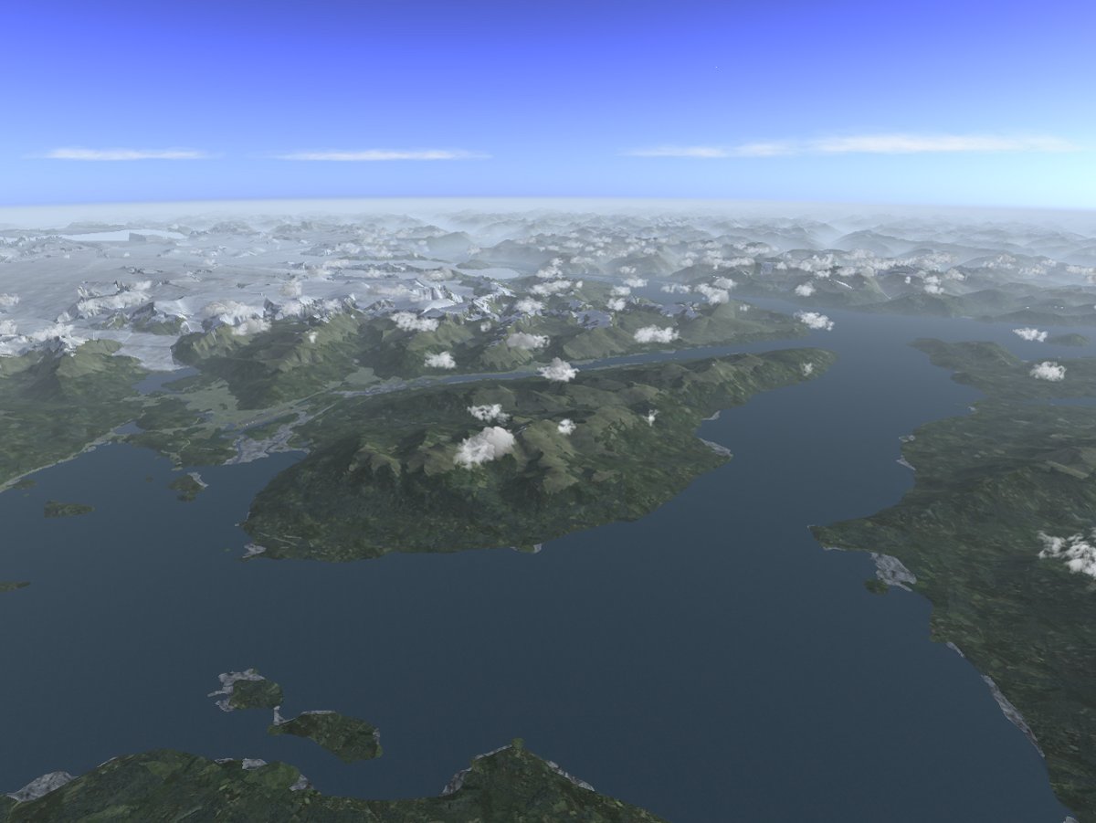
Later in the day, the cloud formation is somewhat stronger. Note how clouds tend to form over mountain peaks, but do not form over open water. Also, no strong cloud development occurs over Taku glacier in the upper left, despite its high altitude, as the ice surface does not heat well in the sun.

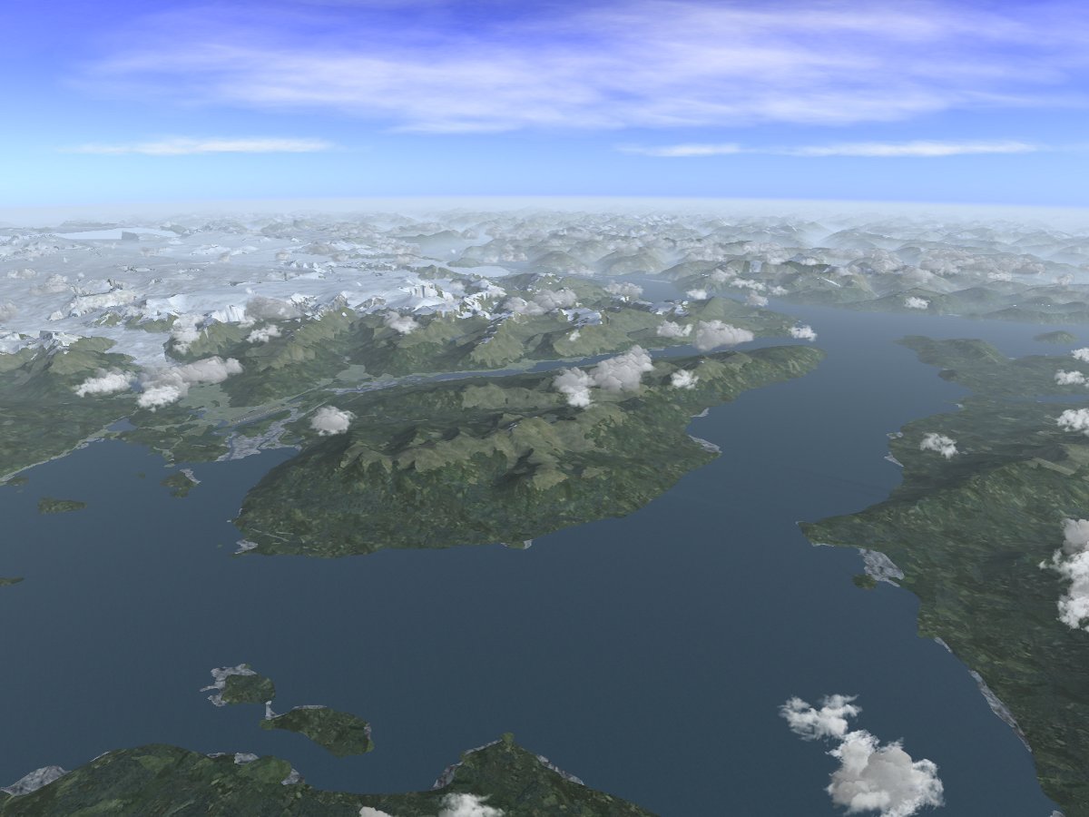
At noon, the thermal updrafts become stronger and consequently the clouds become more well-defined. While in the morning the upward motion of air rarely exceeds 0.5 m/s, around noon this becomes rather 1 m/s, to strengthen even more in the afternoon.

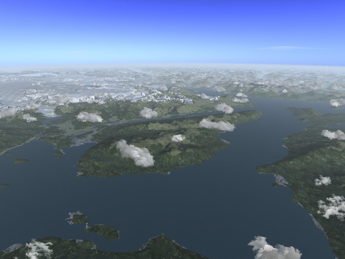
Yet a few hours later, the number of clouds decreases again as the thermal irradiation by the sun weakens, but then typically fewer but stronger thermals with larger cap clouds are found.

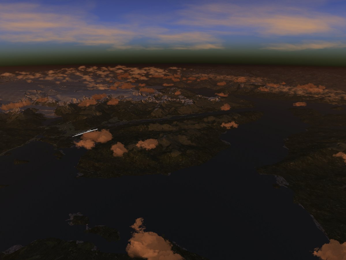
Towards sunset, there is still significant thermal energy left to lead to sizeable cloud development, although the number of clouds as well as the typical strength of thermals is decreasing again. During the night, the development of convective clouds breaks more or less down completely as there is no thermal energy from the sun available.

Interaction of convective clouds, wind and the terrain

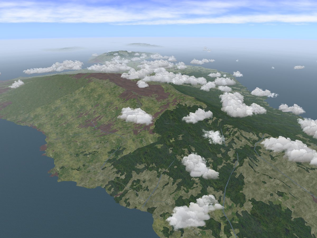
Wind meeting a terrain barrier corresponds to an upward-moving airflow, and hence is able to alter the development pattern of convective clouds in an essential way. Consider the following scene above Maui (Hawaii) in the absence of winds. Clouds rim the peak of Haleakala, but do not actually reach all the way up to the mountaintop (note also that due to the different latitude of Hawaii, there is far more thermal energy coming from the sun than in Juneau, leading to a much higher overall density of clouds):

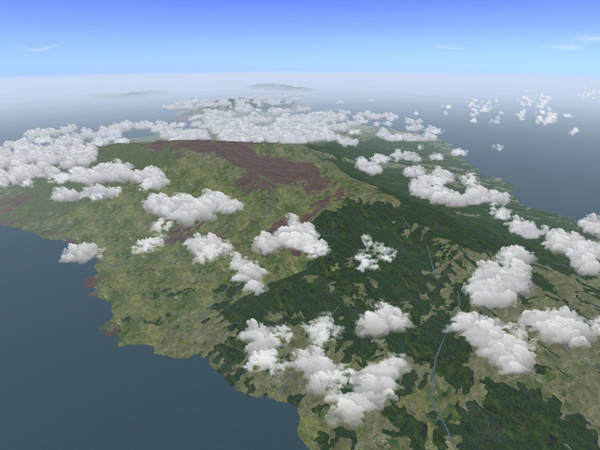
With 20 kt winds coming from the north, the picture changes quite drastically: clouds are now pushed up all the way to the summit of Haleakala by the rising air, whereas the falling air south of the crater creates a lee effect in which convective clouds disappear. The vegetation pattern of Maui reflects these prevaling conditions – while moist air is carried up all the way to the summit of Haleakala, it rains off and irrigates the northern slopes of the mountain, leading to a bright green forest belt. The southern slopes on the other hand see typically falling air and dissolving clouds, and are consequently much drier.

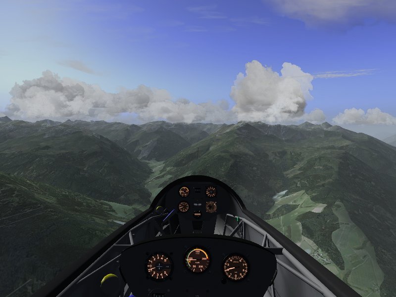
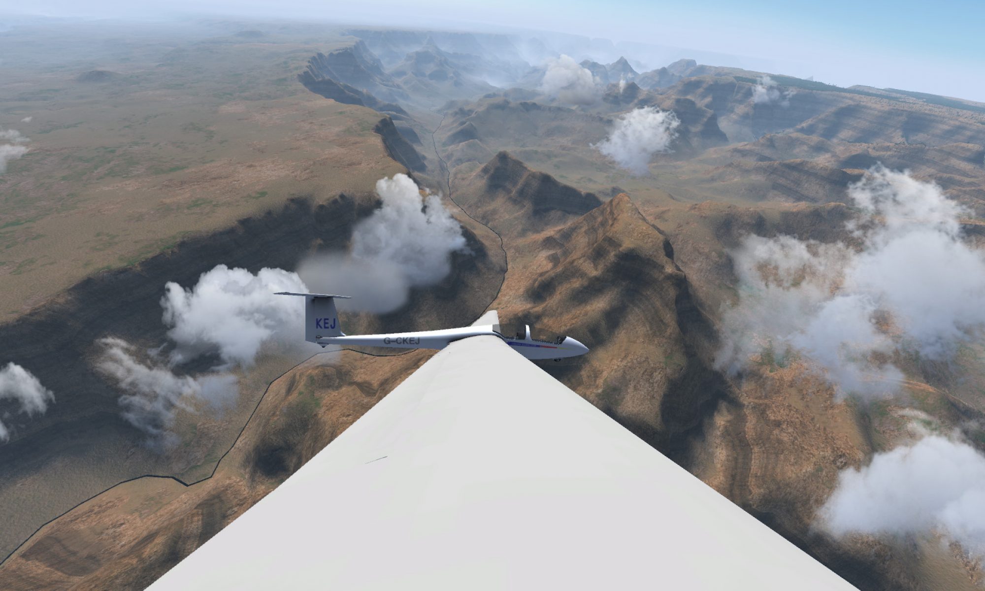
Convective clouds in flight

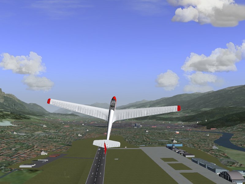
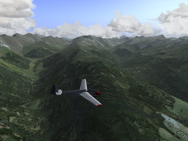
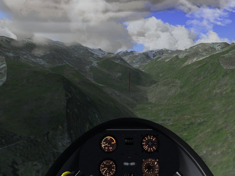
If the appropriate option is selected, thermals are automatically generated along with Cumulus clouds so that thermal soaring is possible. Combined with the effect of ridge lift, this can make for rather realistic mountain soaring conditions in which a good degree of skill is required to stay in the air.

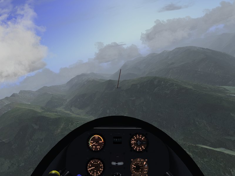
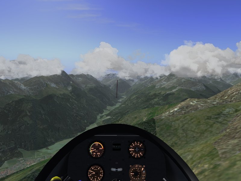
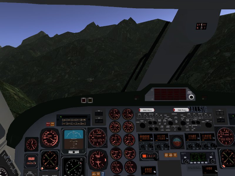
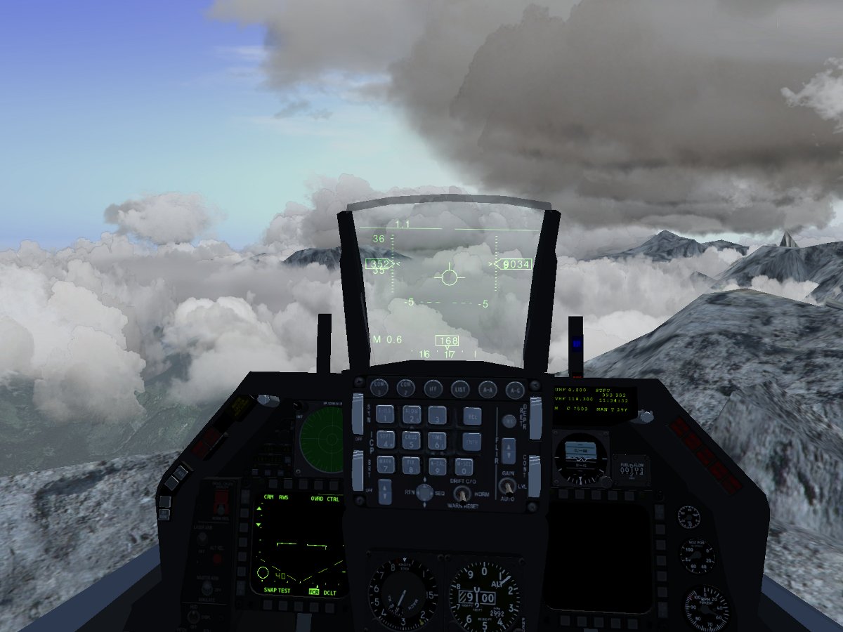
But the detailed interplay between convection and the terrain leads to interesting scenes also in other planes. Around noon, the peaks of high mountains are often covered in rather dramatic clouds piling up against the slopes.

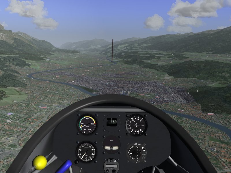
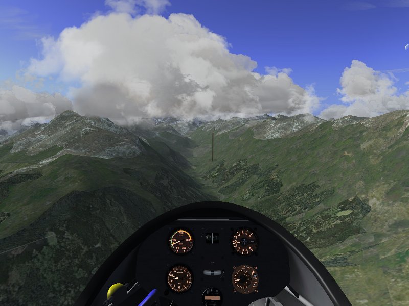
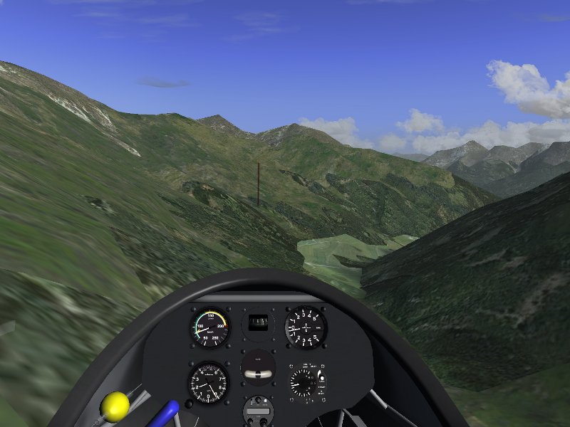
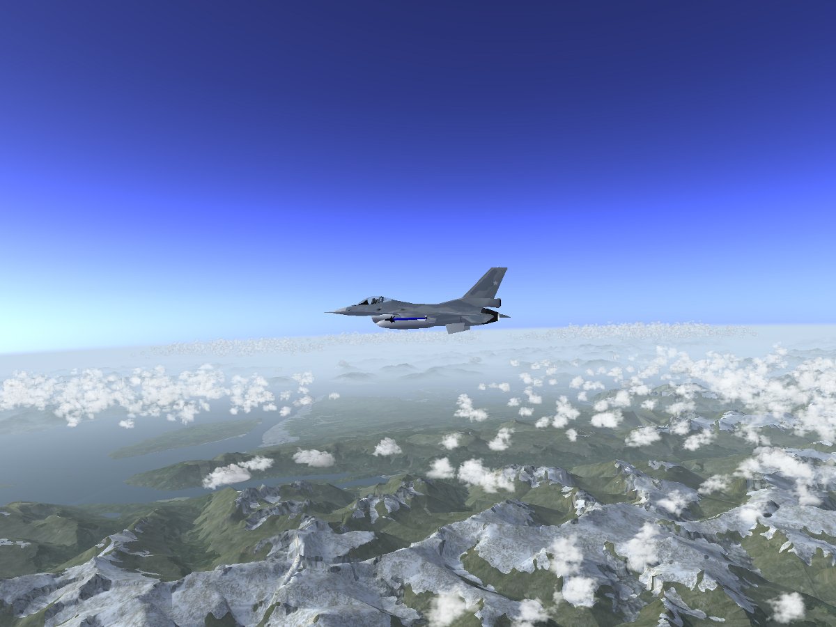
Further down, the altitude of the cloudbase is no longer determined by the terrain but by the air layers.

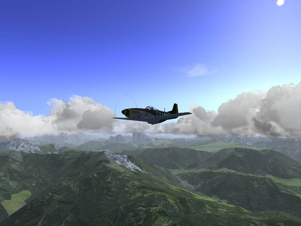
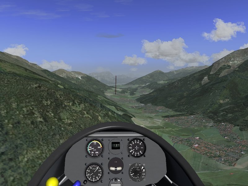
And yet, the terrain elevation and the change between land and water imprint a pronounced pattern onto the distribution of density, shape and size of convective clouds.

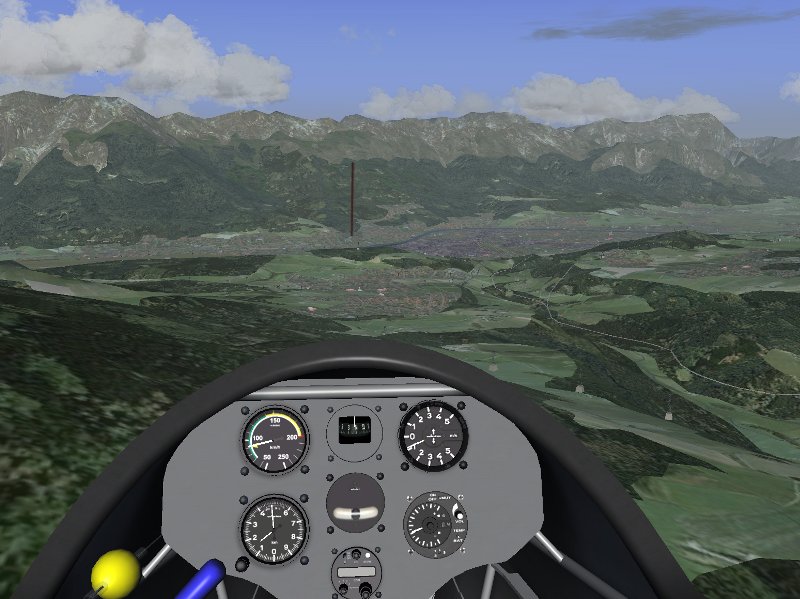
Convection may also occur due to vertical instabilities in upper air layers, leading to the development of Altocumulus clouds, or at even higher altitudes Cirrocumulus clouds. Here’s an example of the development of Altocumulus fields at 15.000 ft. At such high altitudes, the clouds are no longer influenced by the terrain underneath, but rather by the properties of the air layers between which the Altocumuli form. For instance, Altocumulus development may be caused by the instabilities associated with an approaching cold front, and may thus signal the danger of severe thunderstorms in the near future. The Advanced Weather offline weather generation automatically includes this and other rules of large-scale weather patterns.

Next: Layered clouds, haze, fog and precipitation

Sky Diving Visualization

The Challenge

As a skydiver adds more gear such as front packs and items strapped to legs or arms, the jumper’s basic stability in free-fall is reduced.  It becomes easier to tumble out of control and there is less margin for error.  Similarly, the aerodynamic wake of the jumper may interfere with pilot chute opening (known as “hesitation”). Investigating different gear configurations generally involves vertical wind tunnel testing, or actual tests with jumpers. To avoid some of the cost, and mitigating safety concerns, a tool to computationally analyze these jumpers and their gear is highly desired. Creare, Inc., an R+D research firm in Hanover, NH, under funding from the US Army, developed a Computation Fluid Dynamics toolkit for analyzing jumpers and their equipment, and model the resulting configurations in FlightGear.

Note: a flyable parachutist model is available to download and test at the end of this article.

Fluent (CFD) and Stability Derivatives

CFD = Computational Fluid Dynamics.  ANSYS Fluent is a high end CFD that models flow, turbulence, and heat transfer in 3d.   Imagine being able to take a 3d model of a sky diver (or an aircraft) and place it at different orientations and different poses.  Then for each orientation and pose, run a computer simulation of exactly how the air flows around the sky diver, where pockets of turbulence are generated, and what forces and moments are produced.  Imagine all the combinations of roll and pitch and body poses possible — it leads to a huge number of combinations.  Now imagine repeating that for several different arrangements of front and back packs and other equipment.  You will need a cluster of computers running for days or even weeks to compute all the permutations just for a single pack configuration.  This is essentially a “virtual wind tunnel” running on a super computer cluster of PC’s.

In the case of the parachutist simulation: the amount of computation time required to generate 2 scenarios (with a back pack and without) was approximately 25,000 cpu-hours — or around 2 years of compute time on a single processor PC.  1000 individual simulations were run, each involving approximately 4 million “elements”.

One of the detailed CFD models used by Creare


Validation

Real world testing and data collection was performed in a vertical wind tunnel (such as the one linked here.)  This real world data could then be compared to the the Fluent (CFD) results to validate and possibly improve the computer model.

Real Time Simulation

Build-Up of Coefficients:

  • For each component of the model, the local angle of attack and sideslip angle are calculated from the combination of the limb orientation and the overall angle of attack and sideslip of the entire model.
  • For each of the six degrees of freedom, the contribution of the model component to the overall aerodynamic response is calculated from tables of non-dimensional coefficients:
    CFx,y,z = Fx,y,z / ( q * Acomp )
    CMx,y,z = Mx,y,z / ( q * Acomp * Lcomp )
  • The two-dimensional lookup tables are compiled from data extracted from the CFD results in the Solution Database.

Forces and Moments:

  • Aerodynamic forces and moments are transformed from the local frame to the global frame and then summed.
  • Resultant forces and moments then determine accelerations, velocity and turn rates are calculated, and the model iterates.

Creare partnered with Jon Berndt (the founder of JSBSim–one of the core physics engines used by FlightGear) to contribute some clever additions to JSBSim that permit a “blade element” approach to parachutist modeling.  Jon helped tremendously optimizing and integrating the required new code into JSBSim which then ultimately led to its inclusion in FlightGear.  The parachutist physics model is an order of magnitude more complex than a typical aircraft model.

Figure Animation and Posing

The character model is built out of several animated subcomponents: left & right forearms, left & right upper arms, left & right lower legs, left & right upper legs, head, torso, and pelvis.  The model parts are attached in a cascading fashion like a real figure, and each joint can be rotated through all 3 axis (roll, pitch, and yaw.)  In order to avoid unrealistic contortions, sensible joint range of motions are defined.

There are a number of predefined poses where the appropriate joint angles have all been worked out in advance.

  • Box: a neutral pose minimizing rotational or translational motion.
  • Left & Right Translation: mirrored poses that induce a “slide” either to the left or right.
  • Anterior Translation: a pose that induces a forward slide.
  • Posterior Translation: a pose that induces a rearward slide.
  • Left & Right Dorsoventral: mirrored poses that induce a left or right rotation (yaw.)
  • Dorsal: a “spread eagle” pose that maximizes surface area and thus minimizes decent rate.
  • Ventral: a “compressed” pose that minimizes surface area thus maximizes decent rate.
You might notice that these poses map rather neatly into well understood pilot controls similar to flying a helicopter.  For the FlightGear simulation we can mix these poses together in proportion to the corresponding joystick axis deflection and throttle position and fly the sky-diver intuitively.  For those that doubt, this actually works quite well! 🙂

Visualizing CFD Flow-lines

One of the neat things that a CFD analysis can produce are airflow lines that pass around the model.  We can take the 3d flowlines that are produced by the CFD and attach them to the 3d model of the figure.  This allows visualizing the flow lines from any FlightGear perspective.  One interesting technical challenge is that the flow lines need to keep a fixed vertical orientation even though the model may roll or pitch, yet the flowlines must track the heading/yaw of the model.  This can be done by setting up appropriate inverse transformations in the FlightGear model animation configuration file.

Smoke and Trajectory Markers

FlightGear offers additional visualization aids.  The model is set up to support emitting smoke.  FlightGear smoke drifts with the prevaling winds (which can often be substantial at higher altitudes.)  The model is also setup to emit “trajectory markers” at a fixed rate.  The trajectory markers stay fixed in 3d space and represent the actual path the sky diver follows.  In addition they represent the orientation of the sky diver at that point in space.

Where is the Parachute?

This exercise is setup as a free-fall simulation, not a parachute simulation so there is no chute modeled.  Instead the simulation is mercifully paused when the altitude reaches 100′ above the surface.

Download and Fly

Follow these instructions to download, install, and fly the Creare Parachutist model:

  • Note: the parachutist model is not compatible with FlightGear v2.4, you must fly this model with one of the v2.6 release candidates, or the official v2.6 release scheduled for February 17.
  • Download the Creare_Parachutist-v1.0.zip file.
  • Unzip it into your FlightGear “Aircraft” folder.
  • Start FlightGear and select either –aircraft=Parachutist-Scenario1 or –aircraft=Parachutist-Scenario2
  • Make sure you specify  an initial altitude (such as –altitude=10000), otherwise you will just be sitting at the end of the runway working on your tan.
  • Press F1 and F2 to toggle the two available dialog boxes on/off.
  • You can manipulate the joint poses individually or select from a set of pre-defined poses, or select “Joystick” control and fly with a joystick (or keyboard or mouse) similar to flying a helicopter or airplane.

Credits

  • Dietz, A. J., Kaszeta, R. W., Cameron, B., Micka, D. J., Deserranno, D. and Craley, J.”A CFD Toolkit for Modeling Parachutists in Freefall”, presented at the 21st AIAA Decelerators Conference in Dublin, Ireland, 23-26 May 2011. Paper AIAA 2011-2589.
  • The Creare Freefalling Parachutist model was developed by Anthony Dietz (Principal Investigator), Richard Kaszeta , Benjamin Cameron, Daniel Micka, and Dimitri Deserranno of Creare, Inc., as part of an SBIR Phase II project sponsored by the U.S. Army RDECOM Acquisition Center under Contract No. W91CRB-08-C-0135. Additional contributions we made by Curt Olson and Jon S. Berndt as consultants. The resulting parachutist model is unvalidated and therefore, should not be used other than for demonstration purposes. Any opinions, findings and conclusions or recommendations expressed in this material are those of the authors and do not necessarily reflect the views of the US Army RDECOM Acquisition Center.  Due to the significant contributions made to the project by several open source developers,  Creare has released a version of the resulting parachutist model to the open source community for continued development and use.  The FFTK itself continues development as a proprietary Creare project. For information on the FFTK itself, please contact Richard Kaszeta at rwk@creare.com, or 603-643-3800.
  • Flightgear modeling, animation, and scripting – Curtis L. Olson

What would it be like to fly a rocket into space?

Do you want to earn your astronaut’s wings?

Author: Thorsten Renk

Real spaceships aren’t actually piloted into orbit. The risk that a human being, strapped to his acceleration seat and under a crushing acceleration of 4 g for a prolonged period of time is unable to fly with the precision required to reach orbit is far too great, and real spacecraft reach orbit on autopilot.

But what would it be like? Welcome to a scenario in which a Russian Vostok spacecraft has been acquired by the USA and fitted for a manually flown mission.

This is the launch vehicle assembled at Edwards Airforce Base. The actual capsule is hidden under an aerodynamically formed protective cover. Below it is the third stage of the rocket, with its exhaust nozzle visible. All this is mounted on top of the huge first and second stage. Unlike many US rockets, which use sequentially burning stages, the first stage of the Vostok launch vehicle consists of four boosters which burn along with the long, cylindrical second stage.

The inside of the spacecraft is a very small place. There are no big windows (and currently the protective cover blocks the view outside in any case), so there is not so much to see except the instruments. In front of me is the main instrument panel, and to the right is the stage control panel, left of it the control handle.

Here’s a closeup onto the main instrument panel. Since I won’t be able to see anything of the outside during much of the ascent and the descent, this is what I will have to navigate with. The most important instruments are in the lower half of the panel – altimeter, inertial speed indicator, vertical speed indicator, dynamical pressure, orientation and acceleration. This isn’t enough to fly with any precision, say to rendezvous with ISS – but that’s not what the Vostok is for, it’s made to carry a human into orbit and back, and this is what I will do.

One of my most important aids however is a handwritten cue sheet which tells me roughly at what altitude, velocity and orientation the rocket should be at a given time. Without such reference, it is very hard to gauge whether the rocket is on a good ascent path or not.

Unfortunately, the ‘not being able to see too much’ is also a technical limitation. The Flightgear rendering engine is not designed to handle views from low Earth orbit, and even with the cutting edge development high altitude and extreme visibility rendering I’m using in the following, the view doesn’t really measure up to real views of Earth from orbit.

After igniting the engine, the thrust takes a few seconds to ramp up, but the Vostok rocket delivers a solid 2 g initial thrust with first and second stage burning, so I lift off quickly. After the first few seconds, I rotate the rocket around its main axis such that I am facing my launch heading. To make use of Earth’s rotation, launches are done eastward. As soon as I reach the desired heading, I push the ascent path out of the vertical along my launch vector to about 60 degrees with the horizon. During ascent, I will thus be more and more hanging face-down in the capsule, facing Earth at all times. Which is very reasonable, because in case of any instrument malfunction, this gives me at least a rough visual reference. Of course, the actual forces in the capsule are nothing like hanging face-down, the acceleration always pushes me back into the seat.

After passing about 20.000 ft, the dynamical pressure starts growing large, and I have to throttle back to avoid damage to the rocket. After all, a rocket is little more than a thin shell around fuel tanks: For instance, the second stage weighs roughly 100 tons at liftoff, but its empty weight is a bit over 7 tons. The air thins rapidly, however, and thus the dynamical pressure decreases quickly and I go to full thrust again. Once above the pressure peak, I push the nose of the rocket further down to 30 degrees with the horizon and start building up forward velocity while Edwards AFB vanishes below.

The full power of the JSBSim flight dynamics and atmosphere model affects this part of the ascent, and so the interaction between rocket and atmosphere is as realistic as the available data on the Vostok can make it.

After about 90 seconds, the fuel of the first stage boosters is almost spent, and the reduced mass of the launch vehicle ramps up the acceleration to 4 g and beyond. Once again, I throttle back to stay below 4 g to avoid damage to the rocket. At about 120 seconds, the first stage is out of fuel, and I separate the boosters. I am now high enough that air friction is negligible, and so I also blast the protective cover off the capsule and can take the first look outside (nothing much to see though). The second stage is still heavy at this point, and so the thrust goes back to about 2 g as we climb the 100 km altitude limit into space.

The whole flight dynamics changes quite drastically during a mission from the initial launch vehicle to the re-entry of the capsule. Also the weight of spent fuel is a significant factor. All these effects are quite distinctly felt during ascent to orbit.

At this stage, I have to start watching my ascent casefully. The second stage separation should bring me roughly to my orbital altitude with about zero vertical speed so that the third stage burn just keeps me at this altitude while accelerating me to orbital velocity of a bit more than 28.000 km/h. However, the second stage reaches more than 4 g thrust towards the end of its burn, while the third stage starts with barely 0.5 g thust, so any mistake I make at this stage will at best take very long to correct with the 3rd stage burn, at worst be unrecoverable. Thus, I control the pitch angle very carefully and monitor altitude and vertical speed.

About 5 minutes after launch, the second stage burns out and I separate it as well and ignite the third stage. Flying a rocket is very different from flying an airplane – while an airplane reacts to its immediate surroundings and doesn’t remember much of what was five minutes ago, the rocket’s current state is pretty much determined by what happened the last five minutes. If the ascent to this stage was bad, there’s nothing much I can do to correct it now. But my altitude and speed after 2nd stafe separation are within reasonable parameters, and so I continue build up speed while keeping my altitude with the half g thrust the third stage provides.

Another five minutes later, close to reaching orbital velocity, I have to throttle down. The speed must be reached quite accurately, otherwise I might go into an elliptical orbit rather than an almost circular orbit. And this is problematic, because the TDU has even less thrust than the 3rd stage, so if the 3rd stage brings me too high, I might not be able to de-orbit at all.

There are also technical reasons – Flightgear currently isn’t designed to handle an altitude above 150 km, so I have to reach an orbit below 150 km and above 100 km where the atmosphere is thin enough.

I watch the perigee indicator carefully, and as it starts rapidly climbing, I separate the 3rd stage – I am in orbit! Apogee and perigee indicators read 128 km and 140 km, so while not completely circular, this is reasonably good.

Flying to this stage isn’t easy – only three Flightgear pilots have to my knowledge reached a stable orbit with the Vostok spacecraft. You have to work for your astronaut’s wings!

From this point, I only have the minimal thrust of the TDU available to turn the spacecraft and decelerate. Rather than aerodynamical controls, I now have to fire thrusters to change my attitude, so the spacecraft handles once again completely different.

JSBSim handles the attitude control thrusters just as well as the aerodynamical controls, and the spacecraft handles again very plausibly at this stage of the mission.

There’s not much to do while drifting along in the orbit. Look out and watching the sunrise is nice though.

The cutting-edge development experimental lightfield shader brings out the Earth shadow moving across the terrain, the stark shadows in low light and the differential light dependent on altitude very nicely.

To de-orbit, I turn the spacecraft around and fire the TDU main engine to use up the remaining fuel. This lower my perigee such that it intersects with the atmosphere – the friction will have to take care of the rest. Then I separate the TDU as well. At first, the first gentle touches of the atmosphere lead to a tumbling motion of the capsule, this then stabilizes as the drag increases, and I start falling faster and faster.

If you though the 4 g during ascent where tough, then you haven’t experienced re-entry yet. As the capsule finally reaches the lower atmosphere, a deceleration force of 8 g and more brutally brings me from orbital speed to a few hundred km/h. I simply black out during this stage.

Flightgear optionally simulates blackout and redout due to extreme acceleration at set limits.

By the time I get conscious again, I have an altitude of about 10 km and most of the speed is gone. Time to get the brake parachute out and kill the rest of the forward motion. After the braking parachute has done its job, I get the main parachute out, and once my vertical motion has slowed down, the final task is to activate the soft landing sensor.

Close to the US west coast, I gently splash into the ocean. Nothing to do now except to sit tight and wait for the recovery crew to pick me up…

12 Days of Flight Tips (Season 1)

Oscar (youtube user: osjcag) has created a series of short movies called the 12 Days of FlightGear Tips. Each day he releases a new tip in honor of the twelve days of Christmas. Check back each day for the new tip!  Even “seasoned” FlightGear pilots may pick up a new trick or two.  Enjoy!

[youtube]http://www.youtube.com/watch?v=9FSdbw_c9qA[/youtube]

[youtube]http://www.youtube.com/watch?v=NeDMwBMg6Gs[/youtube]

[youtube]http://www.youtube.com/watch?v=HdVCVH0XMXM[/youtube]

[youtube]http://www.youtube.com/watch?v=CLCXwuWvDGQ[/youtube]

[youtube]http://www.youtube.com/watch?v=rITkJyTb5-Q[/youtube]

[youtube]http://www.youtube.com/watch?v=_LcZ93Q33D4[/youtube]

[youtube]http://www.youtube.com/watch?v=0HjkFHatYMI[/youtube]

[youtube]http://www.youtube.com/watch?v=CeFpvAR6sqg[/youtube]

[youtube]http://www.youtube.com/watch?v=hz1c8nuY62U[/youtube]

[youtube]http://www.youtube.com/watch?v=L1aNBV7JBIs[/youtube]

[youtube]http://www.youtube.com/watch?v=hLB7jui1U5c[/youtube]

[youtube]http://www.youtube.com/watch?v=RbB5Sn_ag-A[/youtube]

Soaring with the ASK-13

Soaring in Innsbruck

Author: Thorsten Renk

Innsbruck, 6 am on a warm summer morning just after sunrise. The first members of the aeroclub vacationing with their gliders get out of the tents and observe the weather. There is thin Cirrus coverage overhead, and the first weak Cumulus clouds are forming already. Winds are a steady 10 degrees from East – it looks like a promising day for soaring. I get the ASK-13 out and ready.

(In reality, we would not have the plane out like this in the morning – it’s dangerous to let light planes with excessively long wings lie around in 10 kt winds – either it would have a hangar space, or it would be disassembled in a trailer – but there are some things even Flightgear doesn’t simulate.)

The Local Weather subsystem of Flightgear has a fair amount of knowledge of convection and thermals. For instance, it includes the time into the decision what thermals are formed, and the strength of early morning thermal activity is thus a good guide for the strength later in the day.

Around noon, the thermal activity has significantly increased and thick Cumulus development is seen over the mountain ridges. I’m getting ready for a winch launch in the ASK-13. The ASK-13 is a rather old glider with a glide ratio of 28 optimum (i.e. it covers 28 m distance while sinking 1 m), thus it is not suitable for covering large distances, but it has very good slow-flying properties, and thus it can circle in very narrow thermals.

There’s no need to make a flightplan – soaring can’t be planned. I’ll simply get up there, have a look around and see what possibilities there are, and if I don’t catch a thermal quickly, I’ll land back on the field and do a second winch launch. Soaring in most locations is about finding the thermal updrafts beneath Cumulus clouds and circling them to get altitude. In the mountains, there is additionally the upward deflection of wind by mountain ridges, called ridge lift, which also leads to vicious sink in the lee of the mountains. Flying a glider in the mountains is difficult – often you may have to circle in a confined valley, you may unexpectedly get into a lee and lose a lot of altitude, or you may be forced to land in an unsuitable location.

Flightgear simulates both thermal and ridge lift and (in a very experimental way) in principle also wave lift. Ridge lift is dependent on the wind, terrain roughtness and the local terrain slope, whereas thermal lift is dependent on factors like terrain type and terrain elevation – just as in real life, strong lift does not form over open water but rather over surfaces which heat up in the sun. So, looking for rock surfaces or elevated terrain where a thermal is more likely to form are meaningful in Flightgear as in real life.

A winch launch gets us up into the air quickly – with a good climber like the ASK-13, 500 m altitude are possible (European gliders measure the altitude in meters, not in feet). Winch launch takes a bit getting used to, as it leads to quite rough acceleration and climb more resembling the performance of a rocket than of a plane, but is fun after a while.

The altitude gained in Flightgear winch launches is a bit generous when compared with reality. What launches are supported depends on the plane – several gliders allow aerotow in addition to winch launch. Aerotow allows to get to significantly higher altitude and basically any position, but is in reality much more expensive than winch launch.

Just after disconnecting from the winch, all of Innsbruck lies before us. I’m now turning south, as there are some promising clouds on the slopes there. I have to find a thermal quickly – there are none on the valley floor, so the actual altitude reserve I have are not 300 m above valley floor with 200 m for a safe landing, but far less since I have to look above elevated terrain.

And we enter the first thermal! It’s even a fairly decent one, with a net lift of more than 1.5 m/s. While strong thermals can give lift of 3-4 m/s, starting out low I have to use what I can get – this is not the time to be picky. Properly centering a thermal when entering from below requires some skill – there is no visual reference provided by the cap cloud, so this has to be flown by instruments.

A thermal in Flightgear is not just a uniform area of lift – it has a fairly complicated structure. There is a rim of turbulent air, and an outer layer of sink, the lift is strongest in the center of thermal, the whole column of rising air is slanted and a bit wasp-waisted, so the radius entering a thermal low is smaller than right beneath the cap cloud. Optionally, thermals also have a time evolution, i.e. they form and die off after a while.

After a good ten minutes work, we reach the cloudbase with a good 1500 m more on the altimeter. Now it’s time to go fly some mountains!

The ASK-13 is a twin-seater – a view from the back seat position (taken either by a passenger or an instructor) as we head south into Stubaital – Widdersberg just ahead slightly yo the right.

The ASK-13 can actually take a passenger (sitting on a different computer) via dual control in the backseat position.

Some gorgeous views of the Alps!

Here, I’m using the Innsbruck Custom Scenery, which received a lot of attention also by model developers in recent years, and is hence rather spectacular (see https://www.flightgear.org/forums/viewtopic.php?f=5&t=5350 in the Forum).

Since I’m now hugging a western slope, there is some amount of ridge lift available. The wind is not strong enough for me to really gain altitude, but by going close to the slope I can almost compensate my sink and hence make distance without losing altitude. The downside is that the wind is definitely strong enough to create substantial sink on leeward slopes, so I have to be very careful where I fly.

Heading into a small valley. Soaring is all about realizing possibilities – here the cloud looks very promising, and if I get a good strong thermal, I might even be able to cross the slopes to the right into the next valley. But it will not be easy – the terrain will restrict my circles, so I may not be able to center a thermal properly. I decide to give it a try.

This isn’t going well at all… First, there is some leeward sink coming in, reducing my altitude. Then, the thermal is there, but it is too weak and too small to really lift me up. In the center, I get half a meter of lift, but I can’t keep the plane stationary there, and circling the thermal my net lift is down to almost nothing. Moreover, I am running out of time – the cloud drifts towards the western slope, and I can’t follow it with the altitude I have left – I decide to abandon before conditions become unsafe.

As in real life, a promising cloud doesn’t guarantee a strong thermal. There is some randomness in the correlation between cap cloud size and thermal lift, and even a strong thermal may be in practice not flyable because its radius is too small. The thermal system is not designed to make soaring easy, but to make it a realistic experience, and disappointments are part of the experience. Soaring is not just heading to the next cloud to catch the next lift – one also has to be prepared for the case that no lift can be had there.

Turning around, the situation isn’y actually dangerous yet (in the event, I just need a 50 m strip of relatively level grass to land, which is easy to be had), but it’s not good either. I don’t really want to land in the countryside, because my team might otherwise face a long drive with the trailer to get the plane back. First, I have to head back into Stubaital.

And here we are – plenty of fields to use as landing sites just in case. And a very long way to go back to Innsbruck – all the way to the end of the valley. It looks impossible, but… there is still the ridge lift. Unfortunately, no thermals to help us out of this – the only visible clouds are on leeward slopes, and that’s a very bad idea to try. So I decide to fly very close to the slope to catch most of the ridge lift and try to get back to Innsbruck.

And… it works just fine – with just 50 m altitude loss I make it back – since the valley floor now drops, I have plenty of altitude to spare for my approach to Innsbruck.

Safely back at Innsbruck, and time for the next person to get into the plane and enjoy flying the Alps. I had hoped to fly a longer trip (I did manage to climb above the Habicht once with spectacular views into Italy), but then, soaring can’t be planned, and especially in the mountains, the conditions are often difficult.

A trip to Tenzing-Hillary Airport

A trip to Tenzing-Hillary Airport

Author: Thorsten Renk

One of the most dangerous airports in the world, Tenzing-Hilary Airport, also known as Lukla airport, hugs a small plateau in the Himalayan foothills. It is the gateway for trekkers into the Sagarmatha national park and climbers trying to reach the summit of Mt. Everest. The runway has a length of 460 m and a 12 degree slope – it needs aircraft with STOL (short takeoff and landing) capacities to operate from it. Usually DHC-6 Twin Otter or Dornier Do 228 aircraft, weather permitting, connect Kathmandu and Lukla. Today we will make the trip with the Beechcraft 1900D, a more modern commercial twin-engine turboprop which is also up to the task ahead.

Preflight preparations begin at Kathmandu airport. We will take off before dawn and experience the sunrise in-flight over the mountains. The route is about 70 miles due east from Kathmandu, just along the main mountain range. In good weather, several major summits are visible. Lukla itself is not equipped for instrument approaches, so we have to approach in VFR flight.

Many airports in Flightgear have a set of night textures, making the models visually appealing not only during day but also when it’s dark. Similarly, for many airplanes the cockpit lighting is modelled in some detail. Here, I have switched on the main panel light to illuminate my cockpit during flight preparations. The aircraft models also usually have strobe, nav, taxi or landing lights simulated.

Today, we have broken cloud cover over Kathmandu. As we climb, dawn approaches and the sky brightens, outlining the towering mountain ranges. Kathmandu has an elevation of 4300 ft, Lukla of about 9300 ft, but even this altitude is not even halfway up to Mount Everest with a bit above 29.000 ft. In fact, since the B-1900D is only certified up to 25.000 ft, we wouldn’t even reach the summit at top altitude.

At sunrise and sunset, Flightgear models the different level of light available on the ground and in the air. While it may still be dark on the ground, more light reaches the plane at higher altitude.

A few minutes later, the sun comes above the horizon and sky and cloud lights up while the terrain is still in deep shadow.

For this flight, I am using a development version of Flightgear which experiments with an improved modelling of atmospheric haze layers and shading of the terrain during sunrise and sunset. The result are quite impressive views of the sky. Presumably, this feature will become available with the regular release of Flightgear 2.6.

As we reach Lukla valley, the sun is up and some morning fog hangs in the lower foothills of the mountain ranges.

Now we turn into the approach, and Lukla valley is right before us. There is some fog in the upper valley, but the airstrip itself is clear (it can barely be seen just below the left windshield wiper).

We fly close to the left valley edge to have more space for the final approach. This means crossing some ridges at low altitude and sets off terrain warnings.

Many planes in the Flightgear world have instrumentation which warns about insufficient terrain clearance or potential collisions with incoming traffic.

Now it’s time to turn right into the 060 final approach. The wind is bad – it comes almost right from the rear, but as you’ll see shortly, the approach to runway 30 isn’t exactly available.

Here we are, lined up with the runway. Time to get the gear out and to decelerate a bit.

Some wind drift as we come in – last minute corrections. Lukla is not an airport for missed approaches or second chances – there is a solid rock wall right behind the runway and no chance to pull up. We have to hit the runway now, no matter what happens.

This fairly detailed model of Lukla is an addon to the official Flightgear scenery.

And… here we are, braking real hard.

Welcome to Tenzing-Hillary airport. We hope you enjoyed the flight with us!

In case you find the idea that Air New Zealand would operate in the Himalaya a bit odd, Flightgear offers The Livery Database where many more liveries from all over the world can be found for popular aircraft.

Reconnaissance with the SR-71 Blackbird

Mach 3.2 at 85.000 ft – the SR-71 in Flightgear

Author: Thorsten Renk

Pre-flight

A flight in the SR-71, or the ‘Habu’ as the crews call it, starts long before you enter the cockpit. With the aircraft making Mach 3, you can’t simply fly where you like or take a wrong turn. The Blackbird goes half a mile in the time it takes you to say ‘Oops’, it can be 20 miles in enemy territory by the time it takes you to check a map, and the turn radius is more than hundred miles. This means that basically anything you do needs to be planned in advance.

On longer recon flights, we would have tankers waiting for us in certain locations, but today is just a training flight. We will take off from Nellis AFB, Nevada, go north climbing, then turn around and overfly Nevada at 85.000 ft under mission conditions, then descend and head back to Nellis. All the waypoints for this flight have to be entered into the Astro-Inertial navigation system of the Blackbird in advance.

I am using Flightgear’s route manager to define the waypoints. As in reality, the plane is difficult to control at high altitudes manually, so the autopilot will have to take care of the climb to 85.000 ft. The waypoints need to be defined carefully such that the course is even possible to follow – at service ceiling, the plane is not very maneuverable. I could also, using the AI system of Flightgear, arrange for various tankers to meet me at certain points during my mission if I would want to fly a realistic long range mission profile for the SR-71.

When everything is ready, we finally enter the plane and taxi to the runway. The weather conditions are ideal for reconnaisance – it’s a very clear day with dry air and few clouds.

Many airports in Flightgear have a detailed network of taxiways and one can start the simulation on a specified parking position rather than ready on the runway, and an ever-increasing number of airports also is populated in full detail with 3d models showing not only the main buildings, but also other operations currently ongoing. Nellis AFB is one of the most detailed airports, where one can spend literally hours to explore every detail.

Takeoff and climb

With full afterburners, we gain speed and take off.

The two J58 engines with 34.000 pounts of thrust each sure look impressive with full AB thrust engaged – but the Habu is also a rather heavy bird. Moreover, the engines are designed for high altitude operations, so we just have a thrust/weight ratio of about 0.44, nowhere near to a fighter jet, and so even with full AB thrust, the climb is rather slow.

At about 25.000 ft, we go just a little supersonic for the first time. In this regime, wave drag is very high and the engines actually are not powerful enough to accelerate the aircraft any further. Also, in the thin air, the plane becomes increasingly difficult to handle precisely, and I transfer control to the autopilot.

In order to climb out to full altitude, we have to use gravity’s help and perform the so-called ‘dipsy’ maneuver – we climb to 33.000 ft, level off and let the plane go as fast as it can, then do a shallow dive to about 30.000 ft to let gravity accelerate us to Mach 1.25. Now we’re out of the wave drag region, i.e. drag is much reduced and we can climb further.

Flightgear handles the procedure rather accurately, It is not possible to simply hit the afterburners and fly to 85.000 ft, and if you do not reach sufficient speed at a given altitude, you can’t climb any further. The Blackbird reqires the pilot to adhere to the essential procedures. As in reality, in this altitude it is very difficult to control the plane manually with the precision required for the maneuver, but the autopilot can handle it well.

At the edge of space

Under the control of the autopilot, we continue to climb with a constant KEAS (equivalent airspeed) value of 450 kt all the way up to 70.000 ft, and then let the KEAS value drop to 400 kt while we reach 85.000 ft and Mach 3.2. At this altitude, we’re literally on the edge of space, and utterly alone – no other aircraft can reach this altitude.

The view from 85.000 ft is spectacular on a clear day, and at mission altitude the operator in the back seat becomes busy while the pilot can relax a little since the plane does little but fly straight under AP control.

Flightgear has an experimental skydome shader which tries to solve the physics of light scattering in the atmosphere in addition to the default skydome which handles both foggy and clear conditions reasonably well. The more detailed scattering solution is especially suitable for a thin atmosphere, such as at high altitude or on a very clear day, and it can give quite spectacular results under the right conditions.

At this altitude, the difference between indicated airspeed and the actual speed over ground is very pronounced: While we read just about 400 kt in the cockpit, we’re actually going more than 1900 kt groundspeed.

Flightgear has accurate models for the atmosphere at high altitude and effects like ram pressure taking the difference between true airspeed, indicated airspeed and equivalent airspeed, as well as Mach number to airspeed change with altitude into account. For most planes, these effects are not very prominent, but for the Blackbird they show up rather pronounced.

Returning to base

After completing the recon run, we slow down to 350 KEAS and descend again to 20.000 ft where I switch off the autopilot and resume manual control. In evening light, we head back to Nellis through a scattered cloud layer.

Some more dense clouds hang over Las Vegas as we merge into the approach pattern for Nellis AFB.

Cloud formation is tied to some degree to location: clouds are much more likely to form over the sun-warmed city than over cool open water. Also, terrain elevation plays some role.

The Habu is a supersonic bird – at low speeds it handles like a brick. One needs to be very careful not to lose too much airspeed when turning into the final approach. As compared with other planes, the approach is also really fast to retain enough lift – the Habu approaches with about 220 kt and touches down with litte under 200 kt – more than many propeller-driven aircraft will ever make. However, there remains the problem of deceleration… As we turn into final approach, I arm the drag chute, which is automatically deployed as we touch down.

The JSBSim Flight Dynamics Model handles object like the drag chute rather well as external forces. The drag chute has its own aerodynamical properties, it feels the wind and the drag effect is velocity dependent. As in reality, it takes quite a lot of space to decelerate a plane touching down with 200 kt, and in fact without the drag chute it would be a problem to slow down even given the long runway at Nellis.

After a successful training mission, we reach the temporary parking position of the Habu and head for debriefing, before we leave the base for a nice, cold beer in Las Vegas.

Carrier Ops (USS Carl Vinson)

Carrier Operations in Flightgear

Author: Thorsten Renk

Pre-flight preparation

The flight deck of the USS Carl Vinson, 8:30 am Pacific Daylight Time, off the US west coast: an F-14b is made ready for a flight. The weather is rough, 16 kt of winds coming from the open ocean, with gusts reaching up to 20 kt and changing directions. The Vinson has just crossed a patch of rain, but the clouds seem to be breaking up.

While the ground crew takes care of the plane, the pilot and the RIO go through mission briefing. Our flight this morning will be an intercept training – there is an intercept target north of us which we are to identify.

The scenario is set up using Flightgear’s AI system – both the carrier group and the intercept target are defined as AI scenarios which are defined before starting the simulation. Here I am using a simple setup placing a target on a predefined course – but using Flightgear’s scripting language, it would easily be possible to set up a situation completely unknown to me, or an unknown number of targets, or even a scenario which reacts to my presence in a certain way. AI scenarios can be quite complex – the Vinson scenario simulates the movement of a whole carrier group! The weather conditions can come from live weather reports, or be generated by a sophisticated offline weather system. Many planes in Flightgear (such as the F-14b) offer multi-crew support, i.e. in principle I could share this mission with a human as RIO – in this case however, I’m actually flying alone.

Ready to launch!

We enter the cockpit and close the canopy. While the crew arms the plane (we’ll be carrying a light air-superiority loadout), I am busy adjusting the plane for takeoff. Among other things, I adjust my altimeter to the current pressure and enter the TACAN channel of the Vinson into the left console. TACAN (TACtical Air Navigation) will be my guide back to the Vinson across a cloud-covered, featureless ocean. I also check the fuel loadout – due to the somewhat rough weather conditions and gusty winds, I prefer to take a lighter fuel load rather than launch with all tanks full.

After all preparations are done, I taxi the plane to the launch catapult and it is attached to the guiding rail. I set the throttle to full afterburner – we are good to go. Windgusts blow the catapult steam all over the deck.

Aircraft in Flightgear allow to customize fuel load, and quite often also the weight distribution of cargo, passengers, or in the case of the F-14, the armamant. All this influences the behaviour the plane will show later in the air, thus this is also an important part of pre-flight preparation. For western fighter jets such as the F-14b, radio navigation is done using the TACAN system. Flightgear has both ‘fixed’ TACAN installations (for instance at airbases) which are part of the scenery, as well as definable TACAN channels to be assigned to AI objects. 

In the air

The catapult launches us forward, and will full afterburners roaring our jet is in the air. For a moment the gusty winds shake us hard, but with rolling friction gone the plane accelerates quickly, and as I retract the gear we can climb steeply into the more quiet air above.

The weather simulation distinguishes between the (usually more gusty) boundary layer winds, and the stronger, but less gusty high altitude winds. The thickness of the boundary layer depends largely on terrain roughness, i.e. it is rather thin – as I pull the plane up, I can leave it quickly.

We keep climbing through scattered clouds into a brilliant morning sky.

At 25.000 ft, I level the plane and turn to the planned intercept course. I could use the autopilot for a while, but I enjoy actually flying myself too much.

Many planes in Flightgear have realistic autopilots. In the case of the F-14b, the AP is carefully limited to what functionality its real counterpart can provide – it is a simple system that can level wings, hold an altitude and hold a course, but it cannot by itself follow radio navigation as the more modern systems of other planes do.

As we go supersonic and race towards the intercept target, the wings automatically fold into their delta configuration to optimize for supersonic flight.

However, today we are in for a disappointment: We do not find the intercept target in time, and racing with full afterburner power, our fuel reserves are quite limited. I decide to abort the chase eventually. To be on the safe side, I ask the Vinson for a tanker.

Tankers could have set up in advance as AI scenario, but Flightgear also has the option to call a tanker for aerial refueling right to your current location – which is what I am using now. 

The KA6 used to refuel the F-14b is quite a small plane and difficult to detect visually, but as we ask for a tanker, we get its TACAN channel to guide us into position. However, I decide to track it on the radar instead (as I would for an intercept) and fly the approach by radar.

The F-14b has a fairly radar that is modelled in quite some detail – it has both a scanning and a tracking mode, it provides information about the target heading and groups targets into different types.

Aerial refueling

Getting fuel from a tanker requires some precision flying – the idea is to approach from behind just a bit faster than the tanker, and then to decelerate without dropping altitude just in the right spot. The trick is to gauge accurately how quickly the plane will slow down once the throttle is pulled back – a mistake there will inevitably lead to oscillations around the right position.

With the probe extended, we approach with just above 250 kt into the sweet spot of the KA6.

and finally start receiving fuel so that we can make it back to Vinson

Aerial refueling, both via probe (as demonstrated here) and boom is implemented in Flightgear. Although many aspects are easier than in real life (there is no turbulence induced by the tanker for instance), it is a tricky enough maneuver to master – especially since the AI tankers fly realistic racetrack patterns, i.e. at some point they start to turn!

Back to Vinson

TACAN guides us back to the Vinson. This time, I fly in the subsonic regime. Another 15 minutes later, we start to descend at the position of the Vinson. Here’s the view from the RIO position as we descend towards a cloud later at around 8000 ft.

We overfly the Vinson and its escort group to get into position for an approach.

Then I slow down the plane, extend flaps, the hook and gear and turn into my final approach. Carrier landings, especially in rough winds, are always more of a controlled crash than a proper landing… but TACAN and the Fresnel Lens Optical Landing System are there to help me align properly in difficult conditions.

However, in this case, the unpredictable crosswinds blows me off course.

Weather in Flightgear can change – gust speed and direction may vary on a short timescale, but winds may also change driven by a new weather report in the live weather system or by the dynamics of the offline weather system. 

At this point I decide to go around, so I switch afterburners back on and retract the gear, blast by the Vinson and come again for a second try. After contacting the Vinson, the carrier turns into a new recovery course.

AI control allows to modify the behaviour of Ai scenarios runtime. In this case, I direct the Vinson to a new course better suited for my landing while I go around.

Caught by the wire on the second attempt…

Missing the approach the first time is not too uncommon with the carrier – it’s always better to try again and hope that things go better than to try to force the aircraft down onto the deck when thing are not going right. Even when touching the deck, it’s not guaranteed that the wire catches, so one should always be prepared to yank the throttle forward.

Debriefing

We get out of the plane…

This time, the mission was a failure – we did not manage to reach the intercept target as planned. But this is as life goes – sometimes things do not work out as planned, sometimes something goes wrong with the plane, sometimes the weather does unpredictable things. The important thing is to be prepared to abort whatever you’re doing if it’s unsafe, and to react to the conditions. It’s always better to stay on the safe side than to end the day in flames.

Flightgear has the option to randomly fail systems with a certain probability. Had I wanted, I could have set up the simulation in such a way that my altimeter wouldn’t work. In several planes, even quite detailed emergency procedures are supported, such as extracting gear without pressure in the hydraulic system, or engine restart in the air after flameout.

P.S.

Youtube video of Carl Vinson Ops.  (Best viewed by clicking “Watch on YouTube” and then going “Full Screen”)  Seriously FULL SCREEN and CRANK UP THE VOLUME!!!

[youtube]http://www.youtube.com/watch?v=cvbtSG9cy20[/youtube]

Predator drone video footage circling the Carl Vinson …

[youtube]http://www.youtube.com/watch?v=PK1uxUZaFBc[/youtube]

Eurocopter EC-135: Aircraft of the Week

Eurocopter EC-135

Model

The Eurocopter EC-135 comes with a very impressive 3d cockpit with photorealistic texturing – one example of very few aircraft in Flightgear.

Unfortunately, many of the switches are not yet functional, and the procedures to start the engine are very simple. Some work on support for more detailed procedures would be beneficial for the helicopter. Nevertheless, the realistic looks of the cockpit create a very nice feeling of immersion into the simulation.

The exterior model, for which a variety of liveries are available, is likewise very impressive – it makes use of state-of-the-art reflection shaders and has animations for lights, the rotors and the doors.

If the model crashes, the crash is also (partially) animated by showing the broken rotor blades.

Flight characteristics

Lacking any experience with any helicopter in reality, it is somewhat difficult to judge how well the FDM is done. Helicopters in Flightgear are not easy to fly due to the overall high degree of realism. However, compared with other models such as the Bo-105 or the R-22, the EC-135 handles certainly a bit easier and is a suitable helicopter for a beginner to learn the basics of helicopter flight. Also as compared to many other helicopters in Flightgear, the EC-135 has a rather powerful engine and can quickly climb vertically.

The model shows a lot of phenomena characteristic for helicopters: For instance, the rotors generate a lot more lift in forward flight than in hover flight, which needs to be compensated for when approaching for landing. In slow or hover flight, the EC-135 can swing like a pendulum under the rotor – this is a very nasty condition and difficult to deal with. The torque of the main rotor is clearly felt and must be compensated by the rear rotor, although this is not as tricky to balance as with other helicopters. The helicopter can easily be flown backwards or sidewards – it’s however tricky not to lose control when doing so. Another interesting experience is to hover at high altitude, then reduce lift via the collective – the helicopter drops down rapidly, and one can observe the blades spinning up.

My personal wishlist

More functionality in the cockpit and more implemented procedures would be a very nice addition to the model.

Things to experience

There are plenty of heliports in the Flightgear world. One nice tour is to load the Vinson AI scenario, and, starting out from the carrier itself, visit its escort group (provided you don’t mind that it’s not a US Navy helicopter…). Most of the ships have a helipad where you can land and enjoy the view you usually don’t get to appreciate. Also, many buildings have helipads on their roofs. It’s somewhat tricky to land on such a tight spot, but it can be done, and usually results into a good feeling of accomplishment.

Thorsten