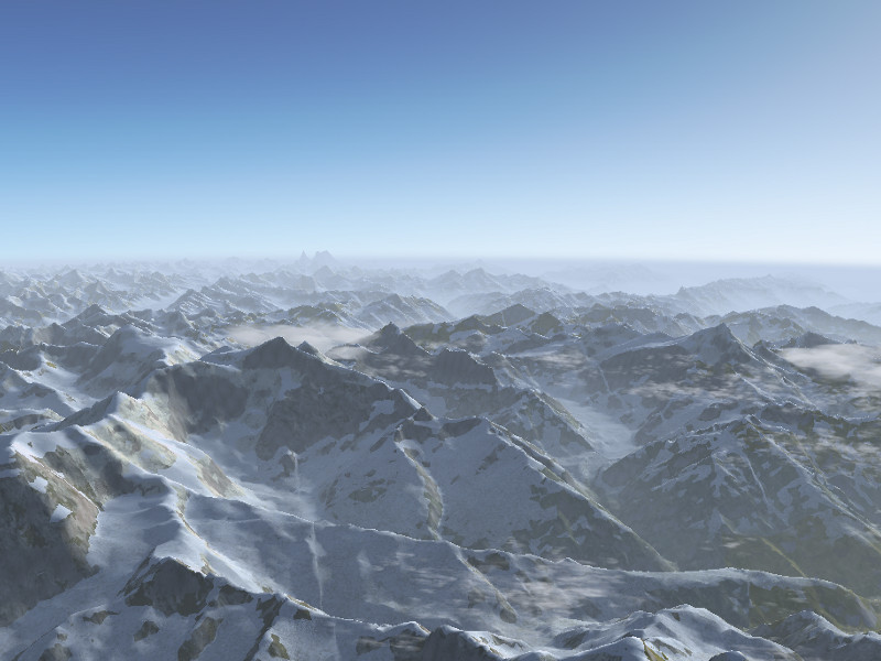
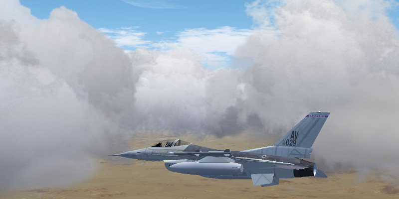
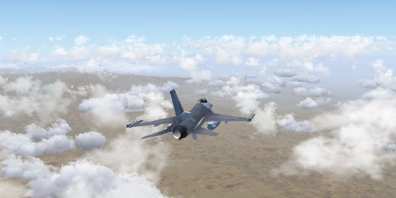
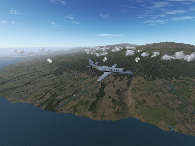
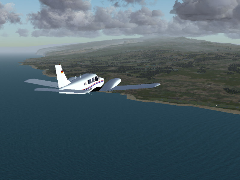
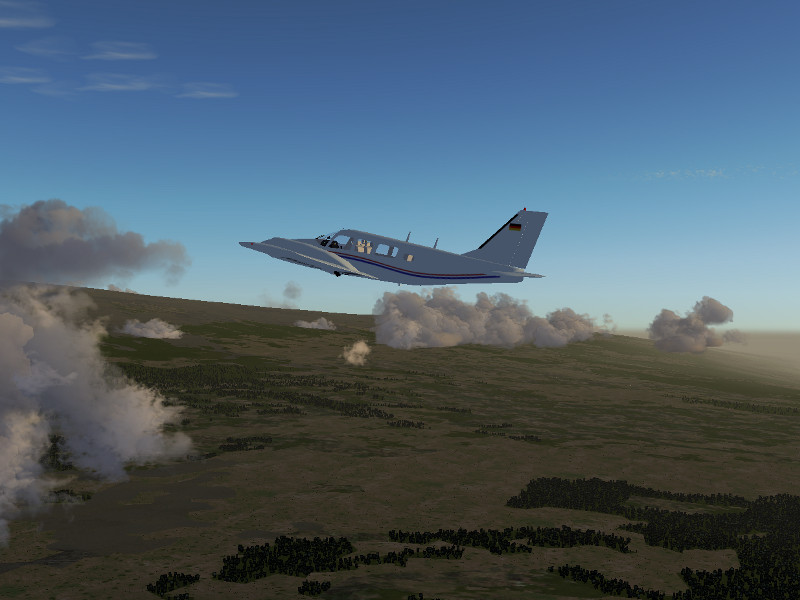
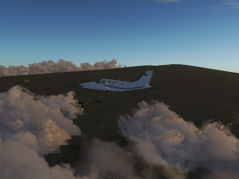
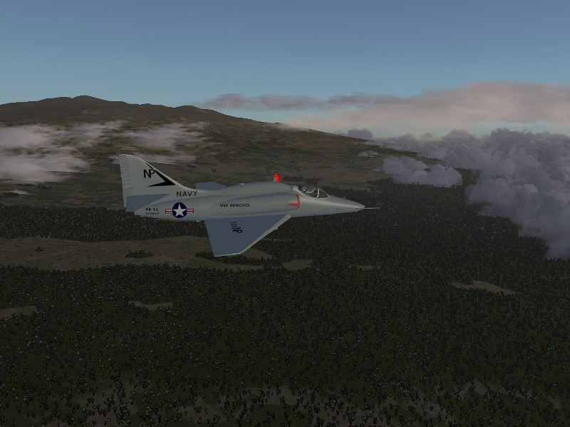
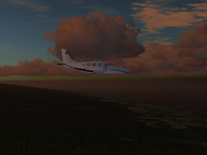
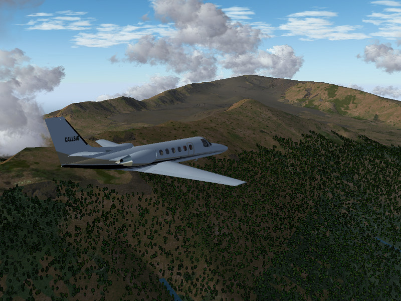
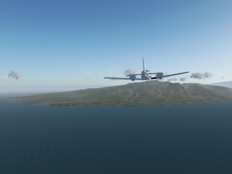
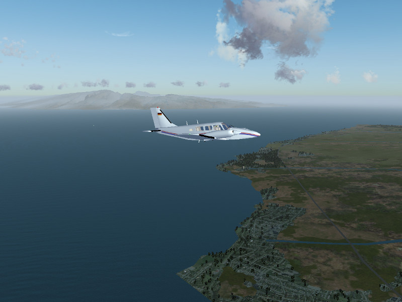
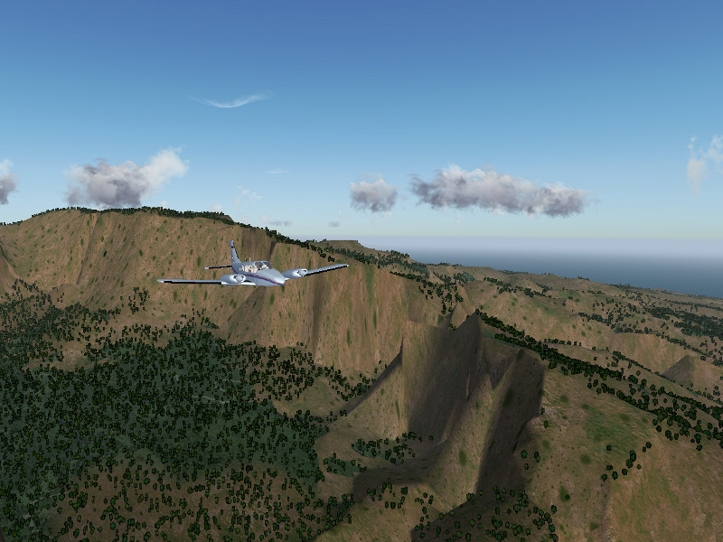
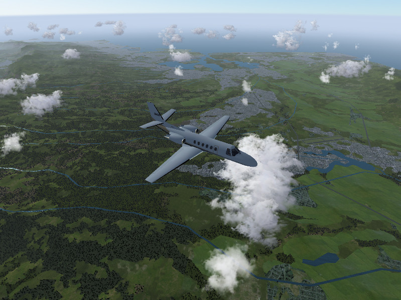
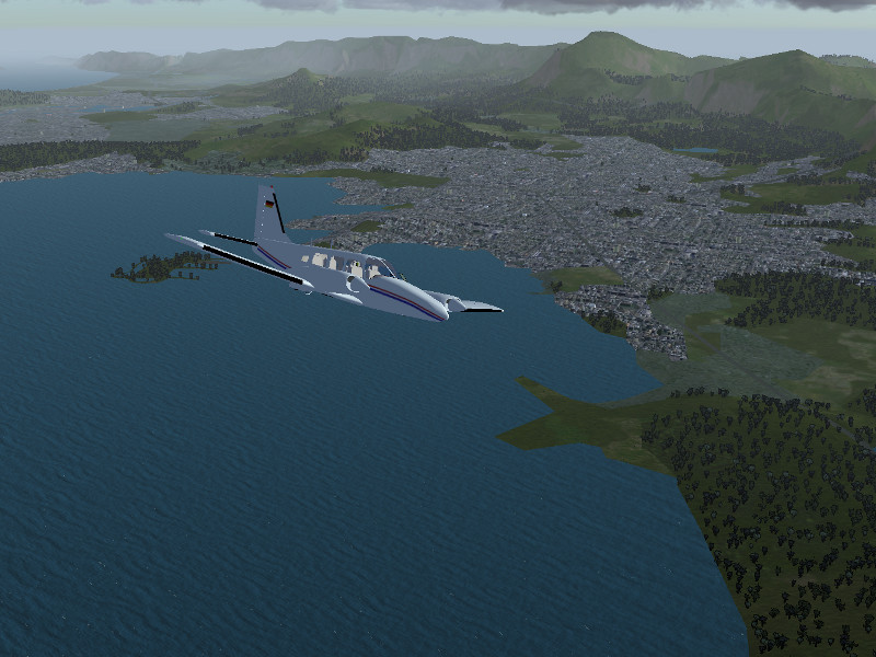
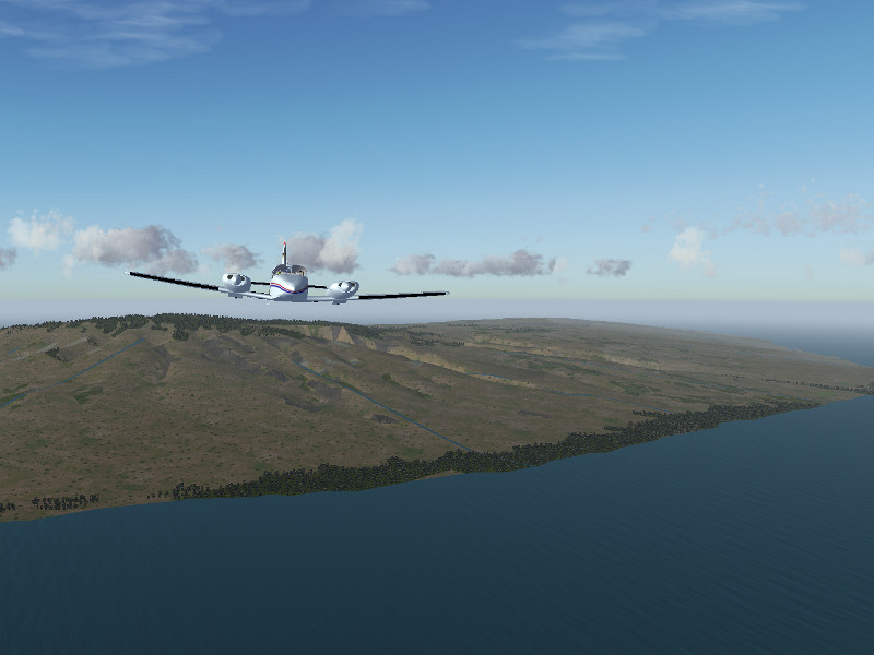
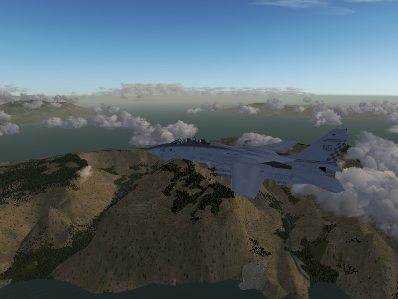
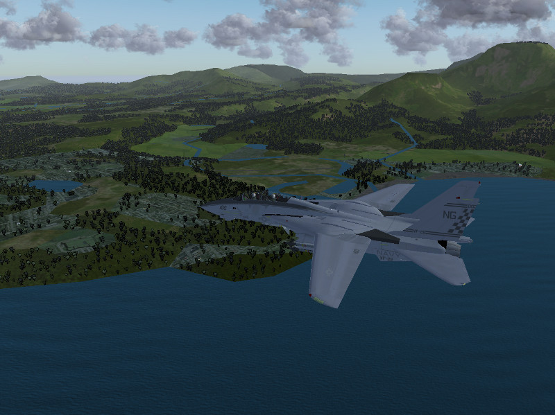
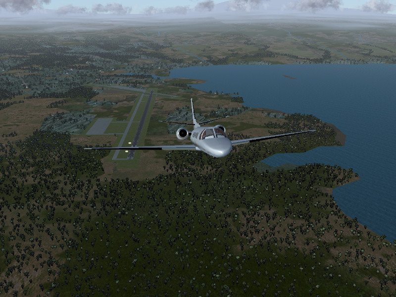
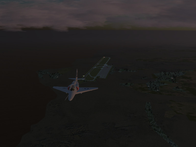
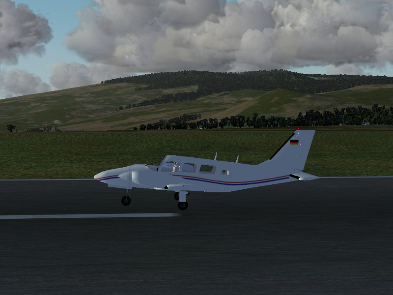
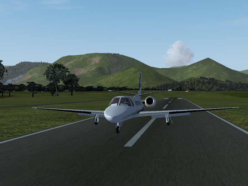
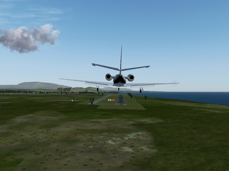
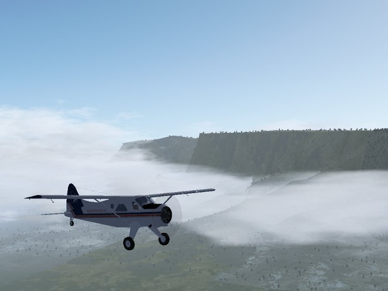
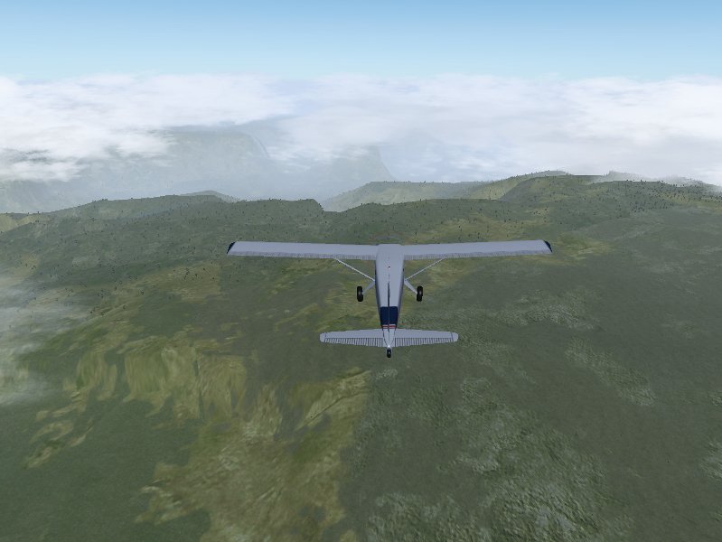
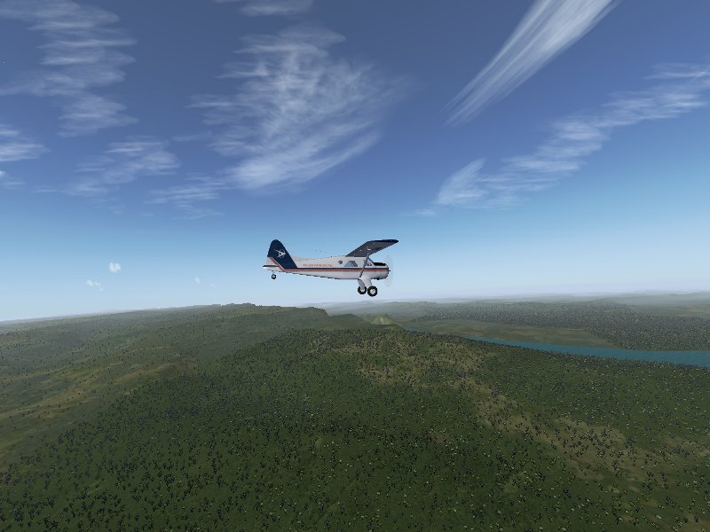
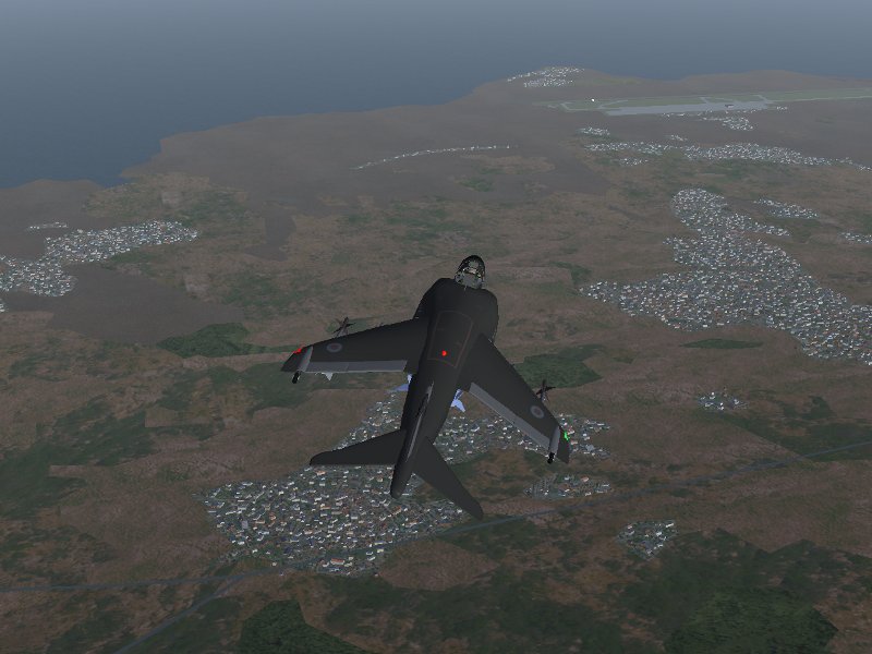
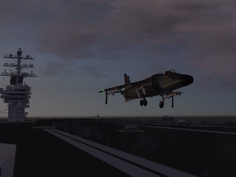
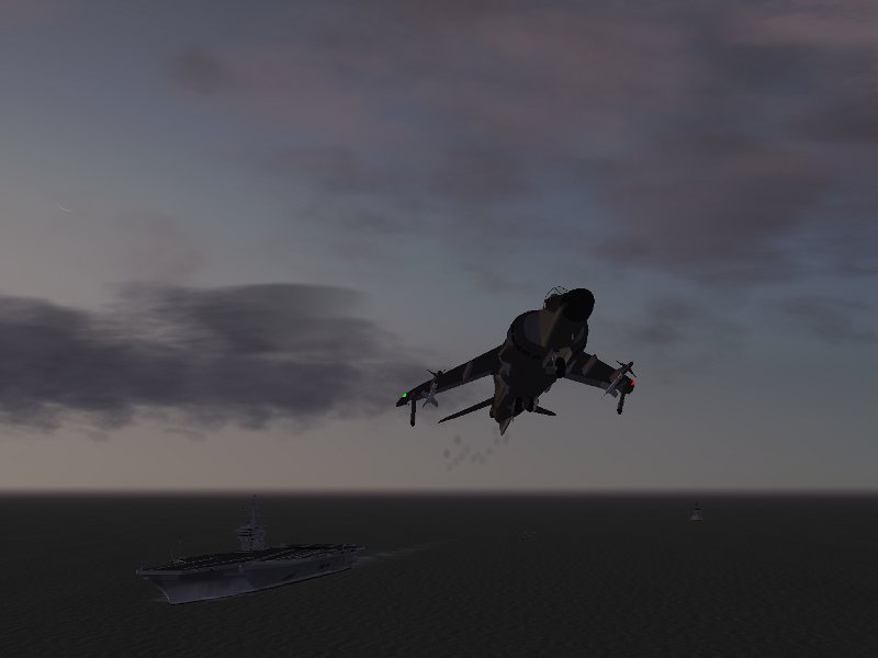
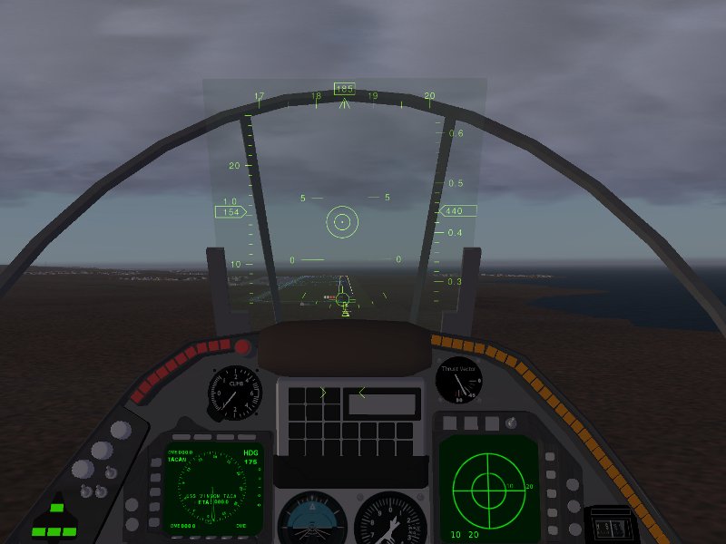
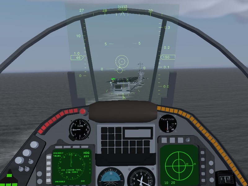
The F-14b is back

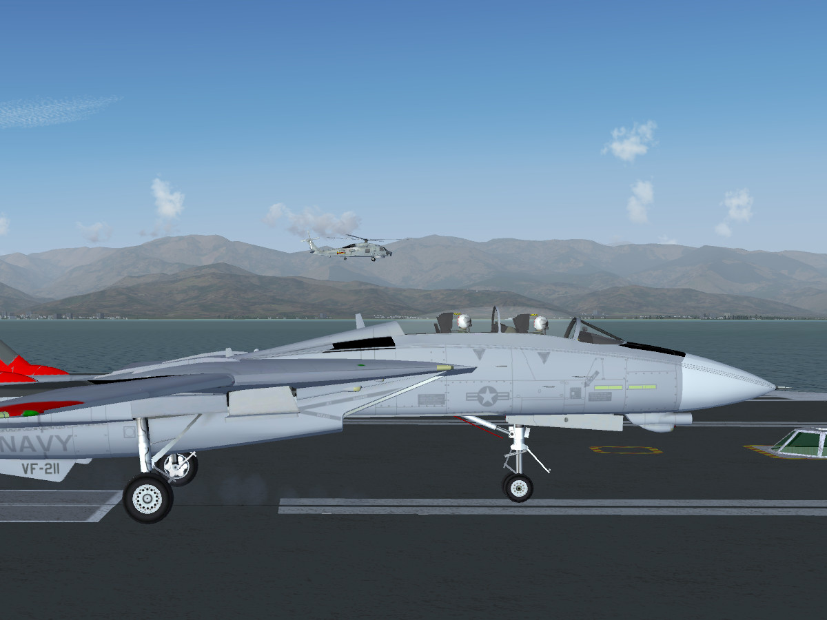
Ready to launch?

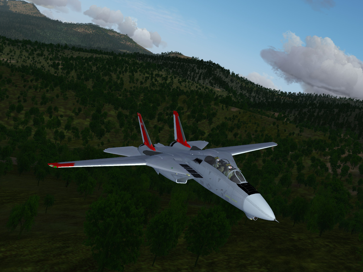
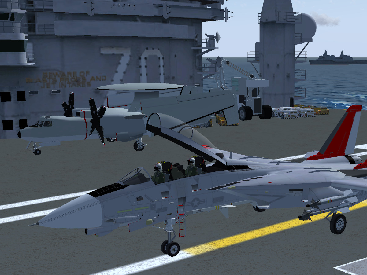
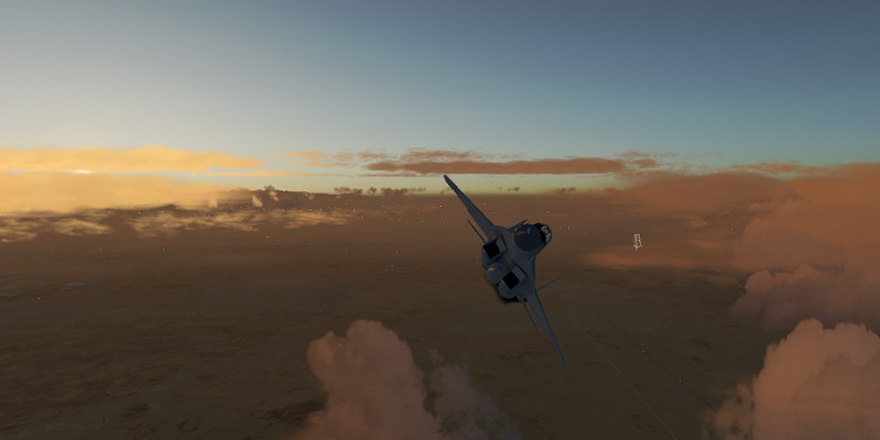
Thanks to Alexis Bory and Enrique Laso, the F-14b has been for a long time one of Flightgear’s most impressive 3d models, with a highly detailed cockpit and a large number of modeled systems.

But it just got even better – are you ready for a ride?

New flight dynamics

Richard Harrison has added a detailed JSBSim model for the flight dynamics based on a number of aerodynamical data sources which makes especially the behaviour at low airspeed very close to the real airplane. This also includes an accurate modeling of stall and departure into spin or flat spin and high alpha control reversal. Wing sweep can be controlled manually and affects the behaviour of the plane,

All of the plane’s control systems are implemented in JSBSim rather than in Nasal (which means they are computed at a much higher rate than the framerate), making the response of the plane more fluid, especially at framerates below 30 fps. All in all, the detailed JSBSim FDM adds quite a lot to the flight experience,

Improved systems modeling

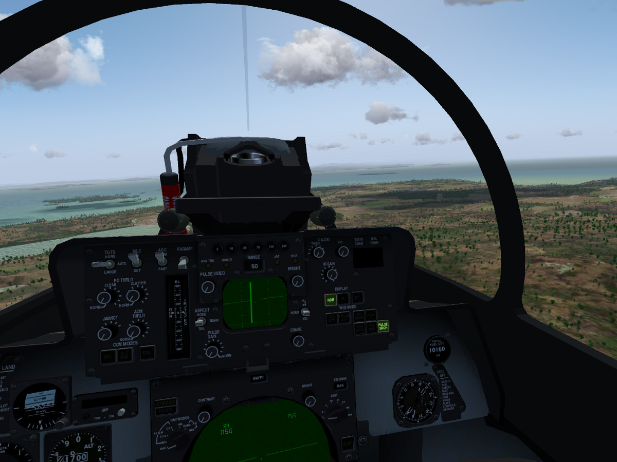
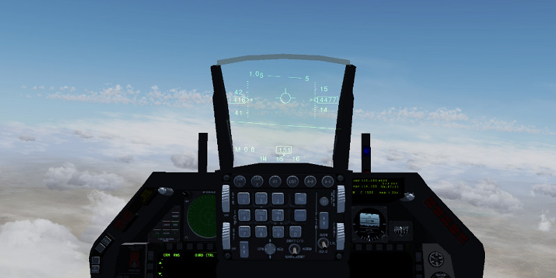
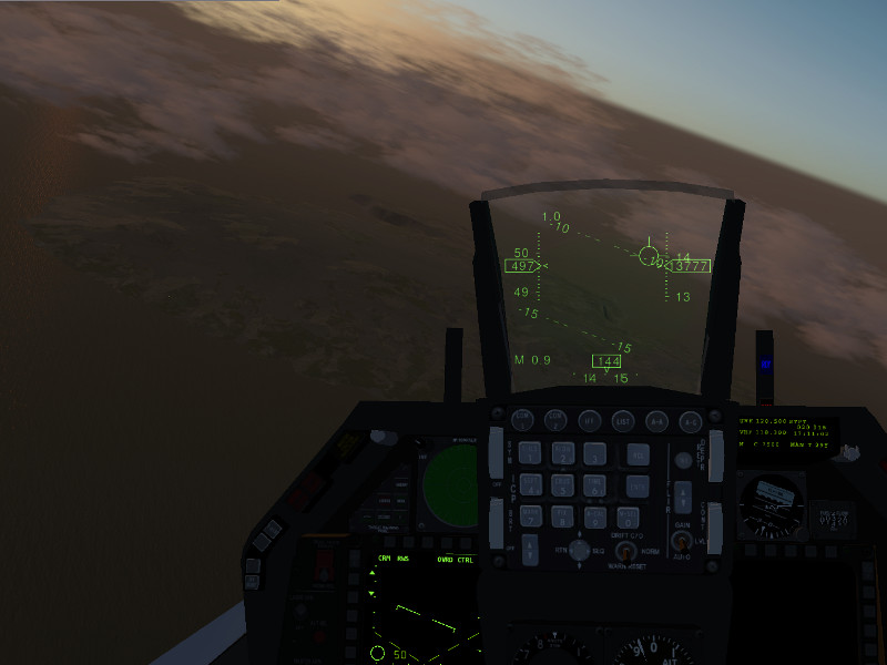
The 3d cockpit has received a number of additions, among them a master warning panel with working indicators, an engine control panel and a master generator control panel. Other switches, such as the fuel cutoffs on the glareshield panel, are now functional, such that an engine startup/shutdown procedure from the cockpit is now possible.

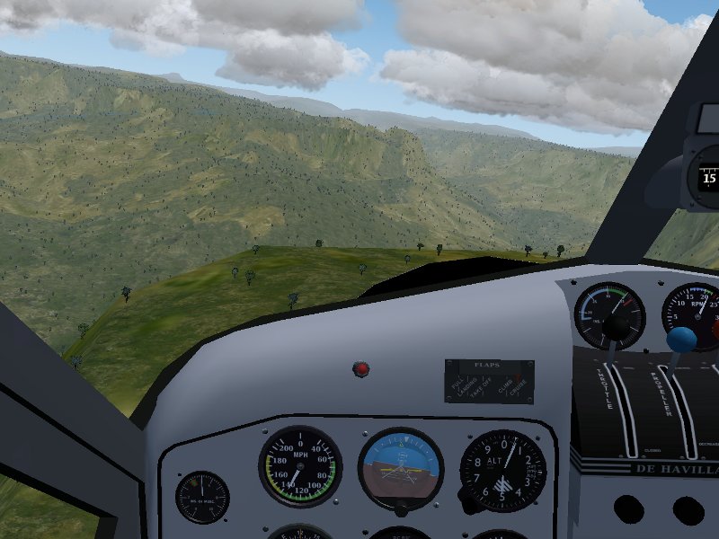
Here is an example of the cockpit view in low-level flight:

And the RIO view:

The full range of operations

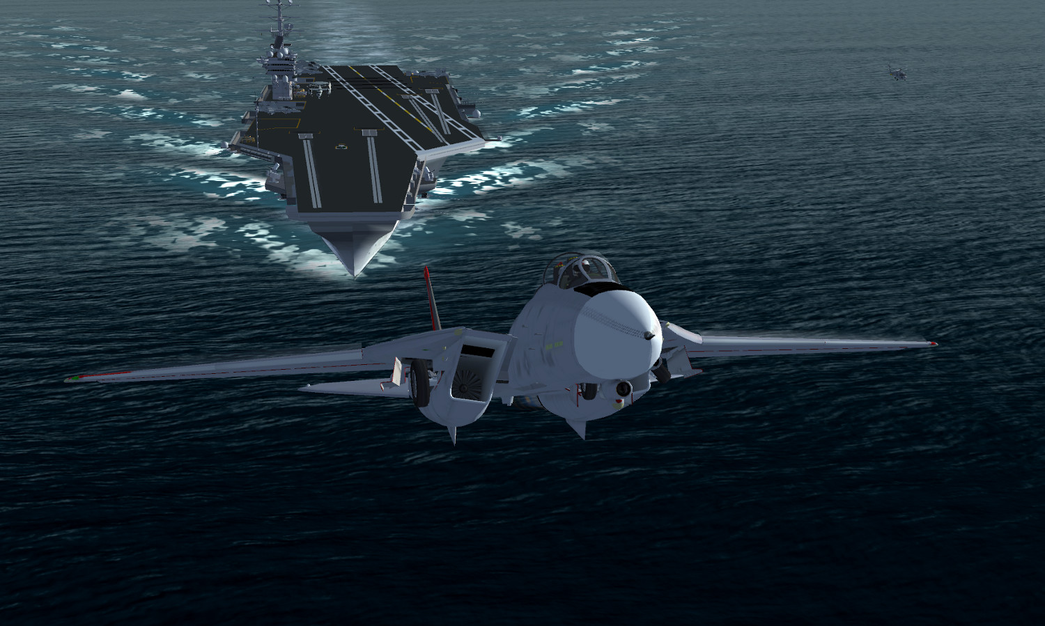
Just like the previous YaSim version, the new JSBSim F-14b supports a full range of military operations. The plane is fully aircraft-carrier capable (due to the improved modeling of low airspeed behaviour, carrier landings are somewhat more difficult than with the YaSim version though).

The plane also has a detailed radar with several different modes, capable of tracking targets, and the operation of the AIM-9M sidewinder missile is modeled as well as the M61A6 Vulcan gun.

Full air-to-air refueling capability from e.g. the KA-6 is also modeled:

Enjoy the new F-14b along with many exciting new features on current GIT (3.3) or with the forthcoming stable release 3.4!

(All features presented in the screenshots (bluish atmosphere haze, details on the Vinson flightdeck, improved appearance of water,…) are available in the current development version and will be part of the 3.4 release. The screenshots have been taken off the coast of Corsica and over Nevada, both in the default 2.0 World Scenery.)

Pushing the boundaries – the X-15 story

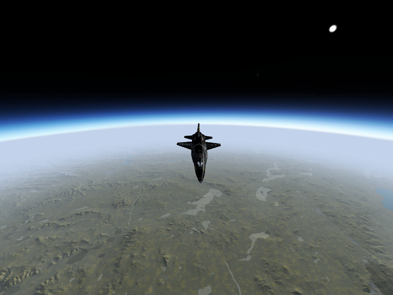
Suborbital flight with the X-15

Going to the edge of space… and back!
Operational history of the X-15

The North American X-15 was a rocket-powered, hypersonic research aircraft operated from 1959 to 1968 by the US Airforce and NASA. During that time, it set a number of records and greatly expanded the knowledge about conditions in the upper atmosphere and in hypersonic flight, thus ultimately laying the foundations upon which the Space Shuttle was built.

The X-15 reached Mach 6.72 on October 3, 1967, which is still today the official world record for the highest speed ever reached by a manned aircraft. In ballistic flight, it reached a top altitude of 354,200 feet (107.8 km) on August 22, 1963, crossing the boundary of space as defined by the Fédération Aéronautique International and making the X-15 the worlds first spaceplane. The 100 km altitude was only crossed on one other flight, but since the USAF defined the criterion for spaceflight by reaching an altitude of 50 miles, 13 different flights met this criterion and qualified the pilots for astronaut status.

Technical data

The X-15 is powered by the XLR-99 using ammonia and liquid oxygen as propellants, giving the plane a thrust of 70,400 lb and a thrust/weight ratio of 2.07. The rocket engine would only burn for about 80 seconds, the smallest part of the whole flight profile, but this would be sufficient to fling the plane on a high reaching ballistic trajectory or to accelerate it to tremendous velocities. It was the first man-rated rocket engine that could be throttled.

The plane has a thick wedge tail for stability at hypersonic flight conditions, however this produces a lot of drag at lower speeds. This means that the glide slope in the unpowered approach back to base is rather steep, and once back in the lower atmosphere, the X-15 sinks rapidly.

For maneuvering in the upper atmosphere where there is no significant air and the control surfaces do not work, the X-15 is equipped with a reaction control system (RCS) using hydrogen peroxide as propellant.

Flight dynamics of the X-15 in Flightgear is based on NASA-TN-D-2532 ‘Flight Measurements of Stability and Control Derivatives of the X-15 Research Airplane to a Mach Number of 6.02 and an Angle of Attack of 25 degrees’.

The RCS is not modeled in the default version of the X-15 available from the Flightgear download page, however an alternative versions of the X-15 with RCS and 3d cockpit are linked below.

Getting ready for suborbital flight

In reality, the X-15 was dropped from a B-52 aircraft at typically 45,000 ft and 450 kt, and then started its engines. This required a lot of preparation, however we also need to prepare the sim for suborbital flight.


Rendering suborbital flight is nothing Flightgear is designed to do, but as it is a very flexible framework, it can still be made to do it. The main problem is opening up the visibility to values which are plausible from the top of a ballistic arc at the edge of space, which amounts to about 400-600 km. This will require a modern graphics card and lots of system memory (the screenshots below were done on a GeForce GTX 670M with 3 GB GPU memory and another 8 GB system memory, this delivered a framerate of ~20 fps at arc top). Trying to open the visibility to large values can have severe performance impacts to the point that FG becomes unresponsive and can crash FG when memory actually runs out – it is recommended to try suitable settings with the ufo before using the X-15.

Some settings need to be tweaked:

* In order for the terrain to be loaded, the LOD range for terrain needs to be set. In the menu, View->Adjust LOD ranges, and set LOD bare to 500000 in order to allow terrain to be loaded up to 500 km distance.

* Loading terrain doesn’t help if the renderer does not display it. The camera of the renderer needs to be instructed not to clip faraway objects. Open the property browser from the Debug->Property Browser menu, and change into /sim/rendering/camera-group/ and adjust zfar to 500000 (or set the property at startup via commandline).

* Finally the weather system needs to be convinced to produce large visibility at high altitude. For Basic Weather, set the visibility at high altitude accrodingly in the mask. Advanced Weather will do it automatically if Max. Visibility in the Advanced Settings is high enough, however the gui doesn’t allow that, hence use the property browser again to set /local-weather/config/aux-max-vis-range to 13.12 (the slider operates on a log scale which is then converted to the actual value).

Switch randon objects, buildings and vegetation off before the flight – you won’t see them, and they will cost a lot of memory which you badly need otherwise. Launching over islands limits the amount of terrain to be loaded, also World Scenery 1.0 with low polygon count works better than he new World Scenery 2.0.

Finally, in the View->Rendering menu, switch Atmospheric Light Scattering on – this will render the atmosphere visuals.

One problem may be that FG can’t load the scenery fast enough. If the OS caches used files, loading the scenery from disk into memory once with an ufo-flight before using the X-15 may help here.

Climbing into space

Start the simulation in air, i.e. using commandline options –altitude=45000 and –vc=450 — this will produce the state of the X-15 just after having been dropped from a B-52. For a semi-historic trajectory, you can start above Nellis AFB (KLSV) and aim at a course of 240 deg which will roughly get you to Edwards AFB and Rogers Dry lake, the historic landing site for the X-15.

Take a few seconds after the drop to stabilize the plane into a shallow descent, double-check all settings and make sure you’re ready. If all looks well, push the throttle forward till the rocket engine ignites.

The XLR-99 delivers significant thrust, and speed will build up rapidly. We’re far too low for this, so pull gently on the stick till the plane goes into a 45 degree climb out of the lower atmosphere.
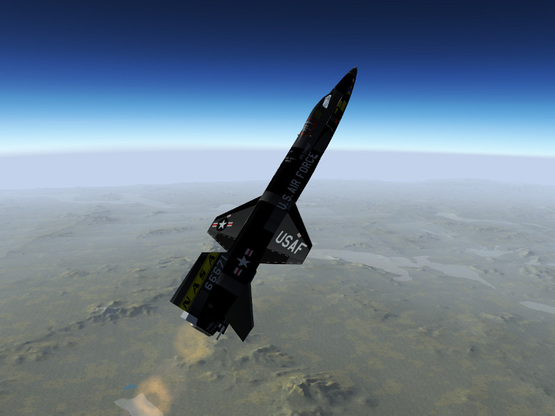
After a bit more than a minute, the main engine will cut out, but the X-15 will climb on. With increasing altitude, pressure based airspeed and altitude gauge become unreliable, so take a look at their inertial counterparts on the right side of the instrument panel now.
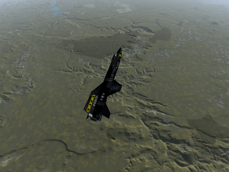
As the ballistic climb continues, the airfoils are losing effectiveness rapidly – time to switch on the RCS! Operate the BAL switch on the right side of the panel, press ‘i’ to grab the stick for RCS control (which in reality would be located on the left side of the cockpit). Think spacecraft now – there’s no damping force left, so operate the thrusters with carefully controlled bursts to stabilize the X-15. Once you have time to look out, you should see a lot of California. And Edwards AFB is really far, far down!
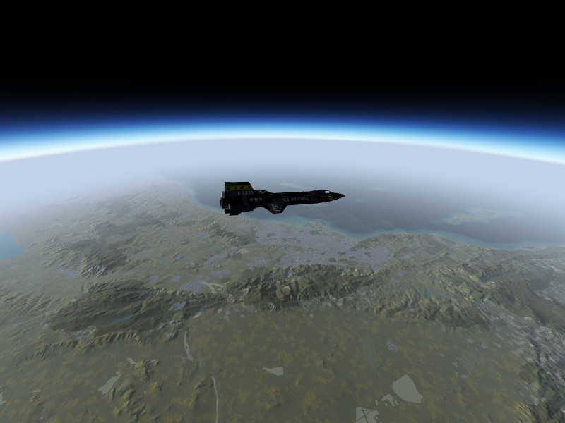
Back to Earth

Now comes the dangerous part — we’re falling down from 330.000 ft, we’re going to be really fast and the deceleration will be hard. The good news is that the view from the cockpit is now quite a bit more spectacular as the planet comes into view.
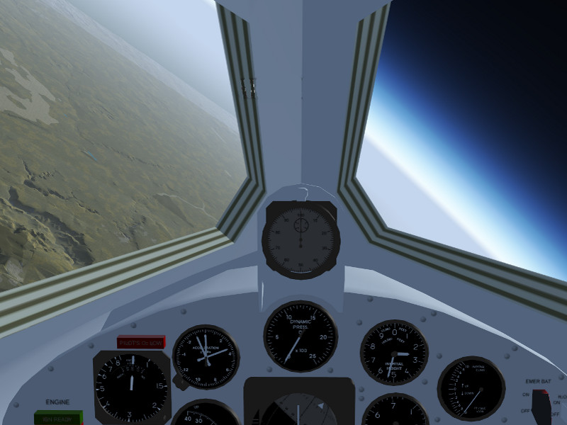
Stabilize the attitude using the RCS thrusters while high up. If the X-15 enters the atmosphere in a spin or roll condition, you will likely not survive the entry. As the plane gets lower, the airflow should start to build up, and if everything is going well, the X-15 should align its nose with the airflow.

The ailerons may become responsive below 200.000 ft already, start switching back to aerodynamical controls using the ‘u’ key and stabilize roll.
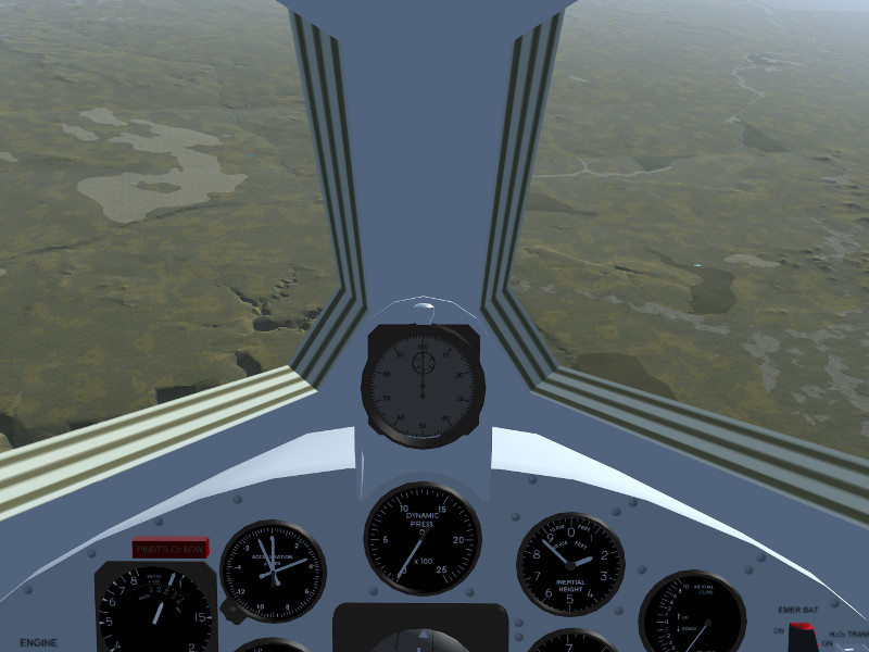
If you’ve been high up, the X-15 is falling really steeply at this point.
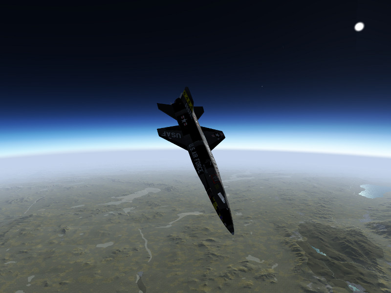
As the ground rushes closer, eventually the elevator becomes responsive as well, typically this starts below 80.000 ft. At this point, the plane will be going really fast and the ground approach rapidly. Pull back on the stick gently and watch the g-force. At this speed, even a gentle pull will translate into lots of force. Expect to experience 6-8 g during the pull out and prepare to black out in the worst phase. This is the most dangerous part of the flight.

Of course, if you don’t want to see a blackout simulated, you can always switch it off in the menu.

If everything went well, you should end up somewhere around 30.000 to 40.000 ft in level flight, with Edwards AFB (or whatever your landing site may be) in convenient reach. Now you can start trusting the pressure-based instrumentation again.

From this point, the drag of the stabilizing fins will be felt badly. Glide the plane maintaining about 300 kt. Rogers Dry Lake is a big place, so planning an approach should be reasonably easy.
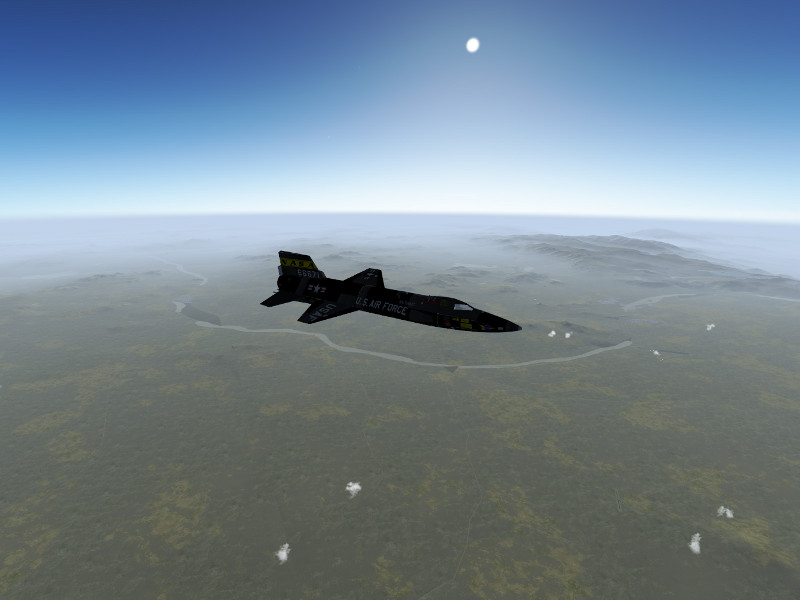
Skids and gear out for the final approach…
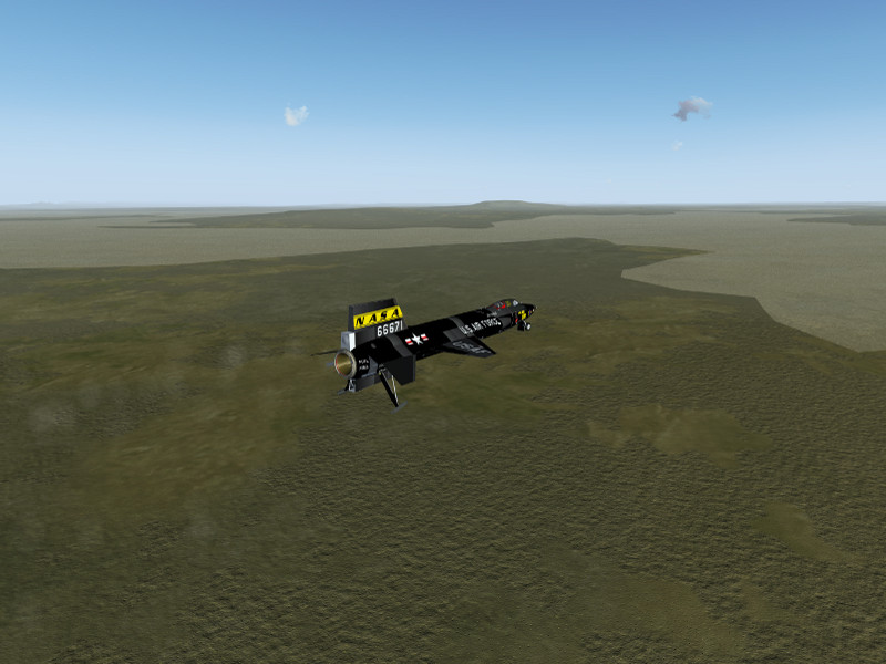
… and a safe landing on the lakebed.

High speed profiles

Historically, the X-15 has not only been flown in high altitude profiles but also in high speed profiles. These are somewhat easier to pilot and control. For a high speed profile, aim at a more shallow climb angle, level off early and try to go horizontal around 100.000 ft, then let the X-15 accelerate and see how fast she will go.
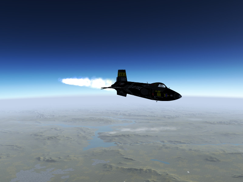
After the engine cuts out, you can simply maintain altitude till the airspeed bleeds off and then slowly descent towards the landing site. Here’s an approach to Edwards AFB from a high speed run, coming in at 60.000 ft now.
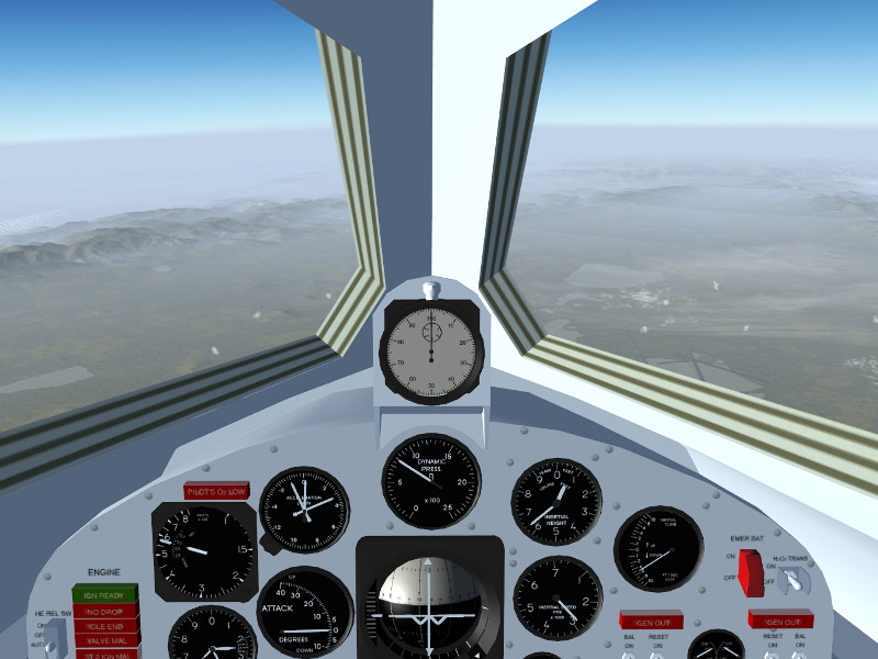
Enjoy flying the first spaceplane mankind has built!

Alternative versions of the X-15

B-52 launched X-15 by Enrique Laso Leon (requires startup from historical location and joystick throttle control)

Free launched X-15 based on Enrique’s version, allowing startup at any location and keyboard throttle control, with some sound effects added.

Special thanks

The modelers of the X-15 in Flightgear:

Enrique Laso Leon
Jon S. Berndt
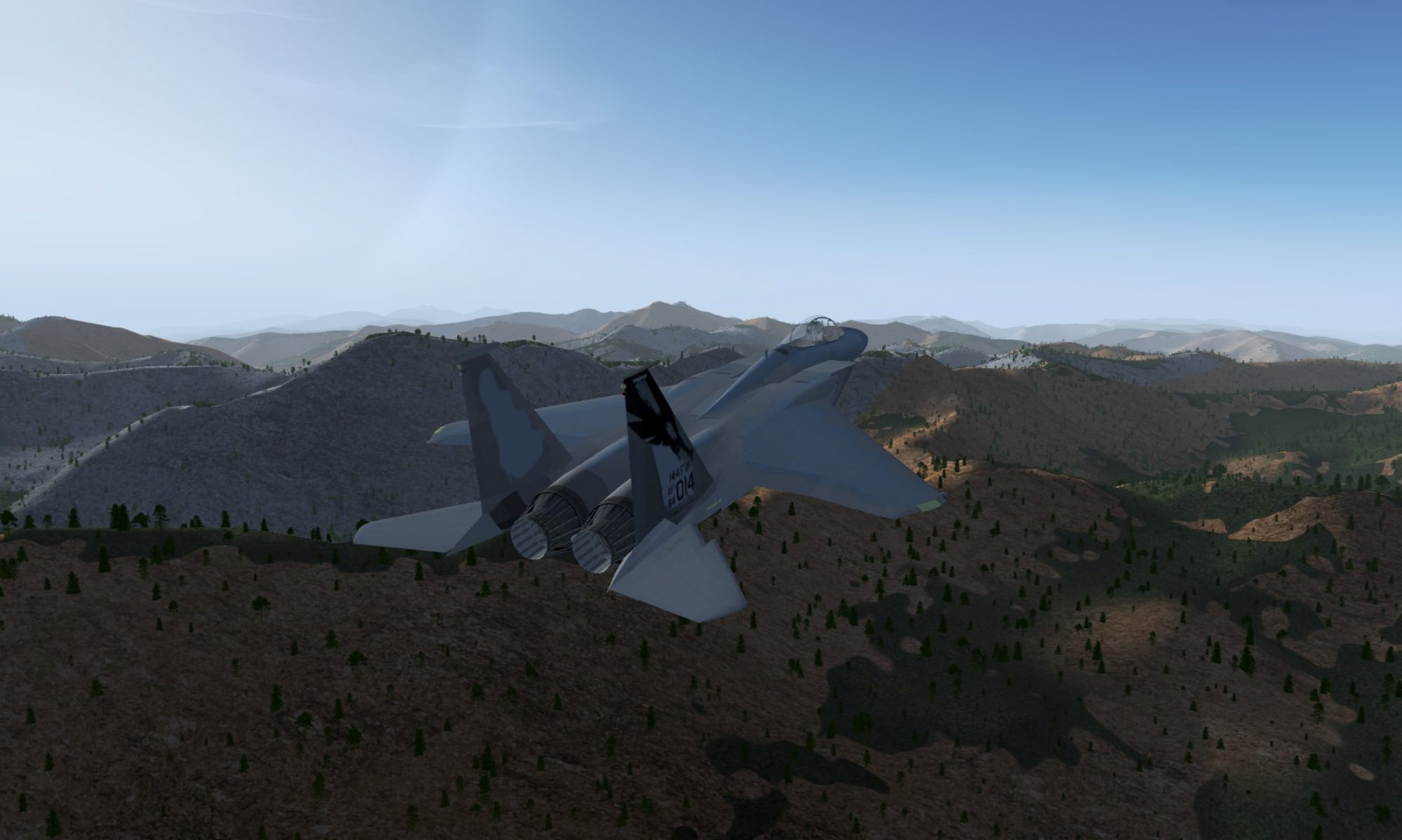
World Scenery 2.0

Together with the release of Flightgear 3.0, a new world-wide scenery is now made available!

Flightgear’s world scenery is based on large-scale processing of publicly available and GPL compatible geodata. There is practically no manual intervention involved, which means that the scenery team can’t decide what quality the scenery will have at a certain location, that is only determined by the quality of the available data.
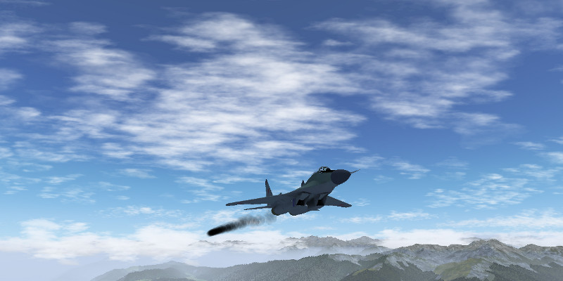
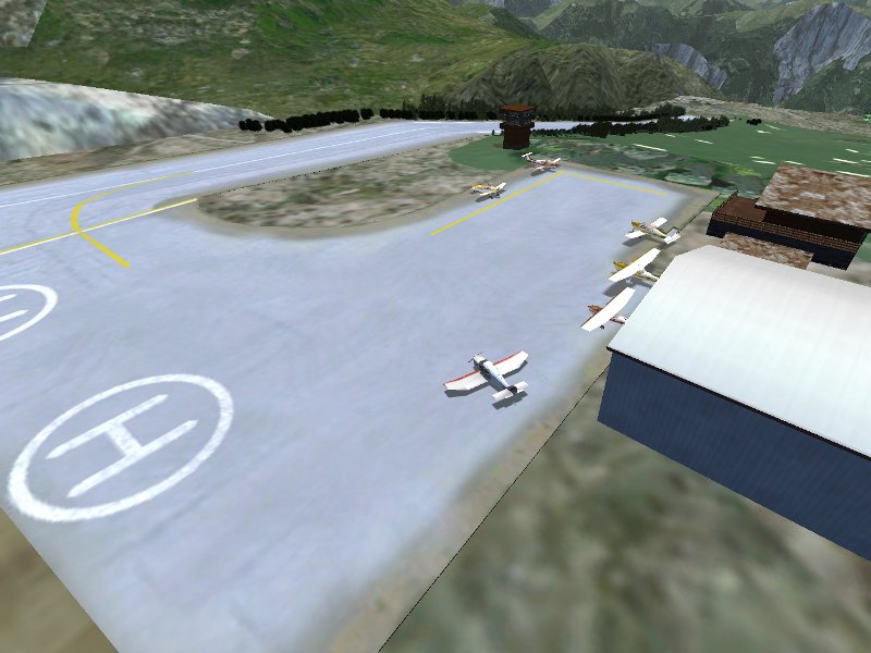
Thanks to the efforts of developers in bringing the processing toolchain up to date, the new official scenery with much better resolution than the previous scenery has now been possible. The new scenery is already available via Terrasync, but it requires a recent version of Flightgear, older versions are not capable of handling the vertex number of the new terrain mesh.

This FlightGear World Scenery was compiled from:
– ViewFinderPanoramas elevation model by Jonathan de Ferranti
– VMap0 Ed.5 worldwide land cover
– CORINE land cover 2006v16 for Europe
– Several custom land cover enhancements
– The latest airports (2013.10), maintained by Robin Peel of X-Plane
– Line data by OpenStreetMap

In general, airport layouts are now improved and updated all over the world, major roads and rivers are drawn to much higher accuracy than previously and the elevation mesh resolution is increased everywhere.

Europe

The most stunning improvements are found in Europe, where in addition to the increased resolution of the elevation mesh, also the CORINE database provides high resolution landcover data. This makes the visuals both in mountain regions as well as plains much more applealing. Combined with regional texture schemes and procedural texturing, an almost photo-realistic effect can often be achieved.

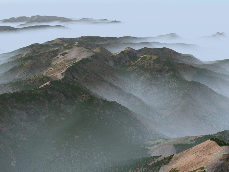
Corsica, France seen from above in morning fog (utilizing Mediterranean texture scheme) :

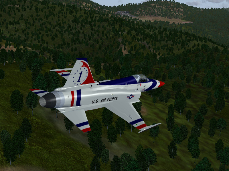
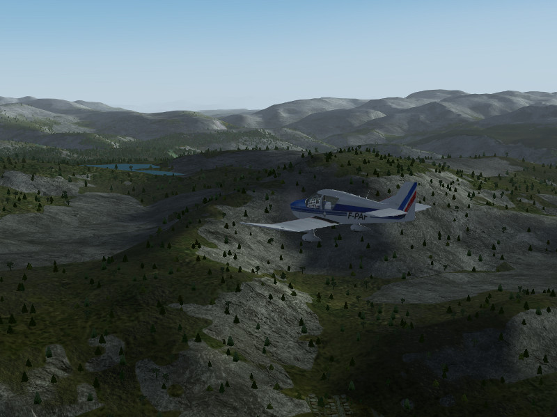
Details of Corsica, France in low-level flight with the F-20:

Fjell lands in Norway (using Scandinavian texture scheme):

Norwegian fjordlands:

Ouside Europe

In the absence of CORINE data, improvements in the landcover rendering are not as dramatic, which leaves flat terrain largely comparable to the previous version of the scenery. However, mountainous regions benefit enormously from the improved elevation mesh resolution. The rendering of light and shade, transition shader effects and snow effects all key on elevation gradients and allow in essence to render the terrain with much more visual detail despite the lack of detailed landcover.

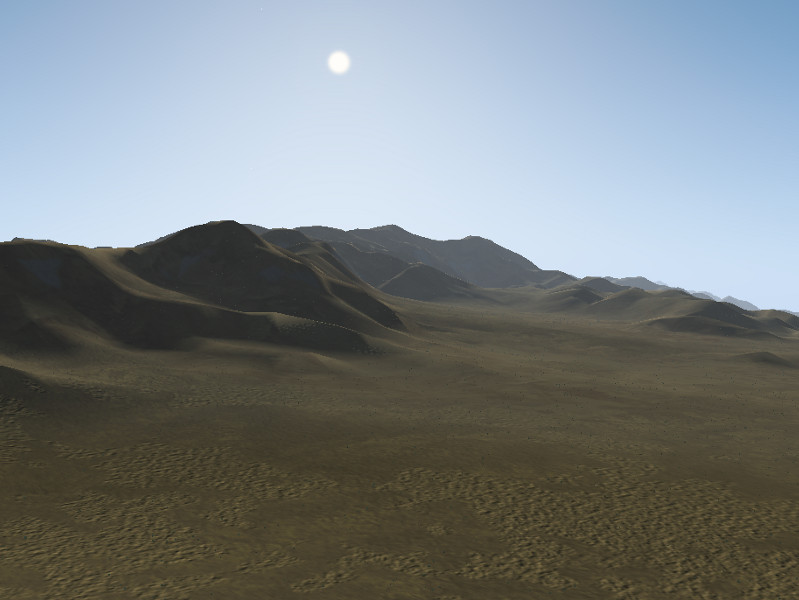
Desert hill chain near Tabas, Iran, seen from the ground (using Middle-East texture scheme and dust shader effect):

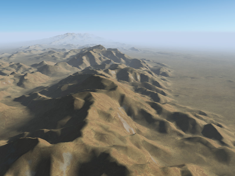
As above, seen from the air:

The Grand Canyon, USA (using dust shader effect):

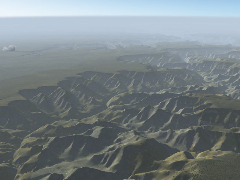
View of the Grand Canyon, USA from high altitude:

Nanga Parbat, Himalaya, Pakistan seen across the Indus valley:

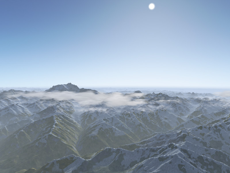
Himalaya north of Nanga Parbat:

Thanks

Special thanks to the people involved:

John Holden
Olivier Jacq
Vic Marriott
Julien Nguyen
Gijs de Rooy
Christian Schmitt
Martin Spott
James Turner
Markus Metz
Pete Sadrozinski

The art of cloud and weather rendering

Author: Thorsten Renk

Advanced Weather

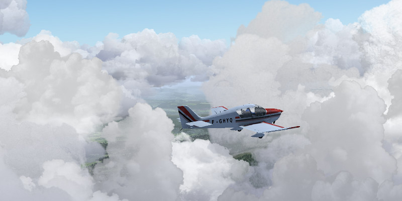
Advanced Weather is one of Flightgear’s two weather-generating systems. It operates based on a (limited) understanding of atmosphere physics – the user selects a weather situation, either from the menu or via specifying a METAR string, and the system simulates the weather from there. For instance, once the system knows how unstable the lowest layer of air is against convection, it automatically decides on the presence of thermals, turbulence, convective cloud number and visual appearance. In this way, generated weather matches cloud types in the different layers based on what would typically also occur in reality for the given weather situation.

The system renders practically all clouds in 3D. To get close to a real sky appearance, it utilizes a large variety of algorithms grouping cloudlets into layers, streaks or undulatus patterns. Combined with the ability to change the weather as a function of position, endless varieties of weather situations appear, and both in the online and offline weather modes, the sky never really looks the same.

Simply select a basic weather scenario and watch the cloud patterns change from high or low altitude!


Clouds and the terrain

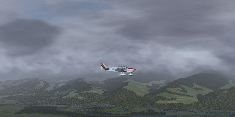
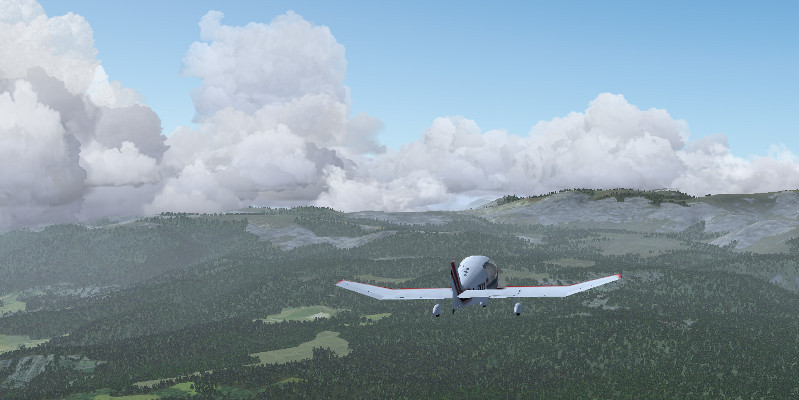
Cloud layer placement in level terrain is a simple exercise, but to render weather properly in mountain areas is a challenge. The weather system continually receives information about the terrain surrounding the plane, from which the distribution of wind and turbulence close to the ground as well as the placement pattern of clouds is computed.

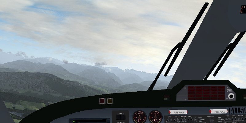
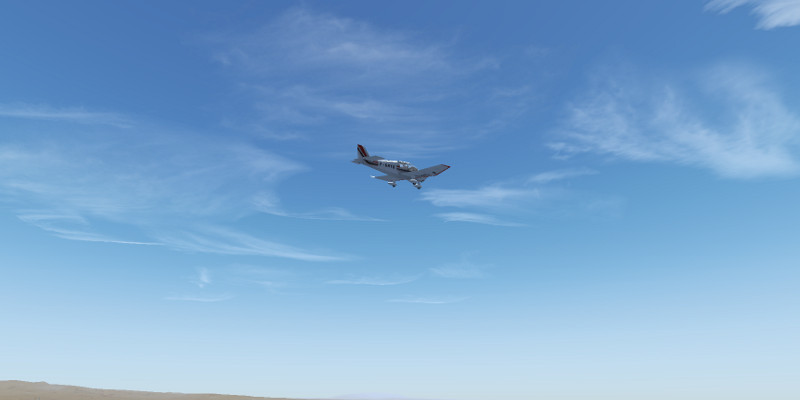
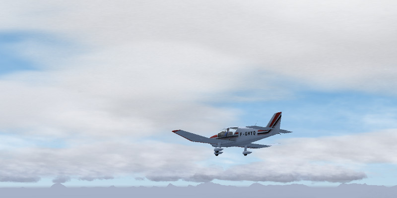
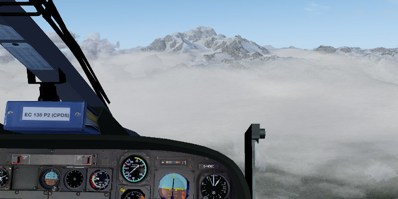
Try flying a mountain rescue helicopter in bad weather to see the weather system in action! Or simply go sightseeing in the mountains with a single-engine plane.


Precipitation and turbulence

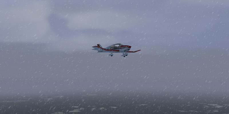
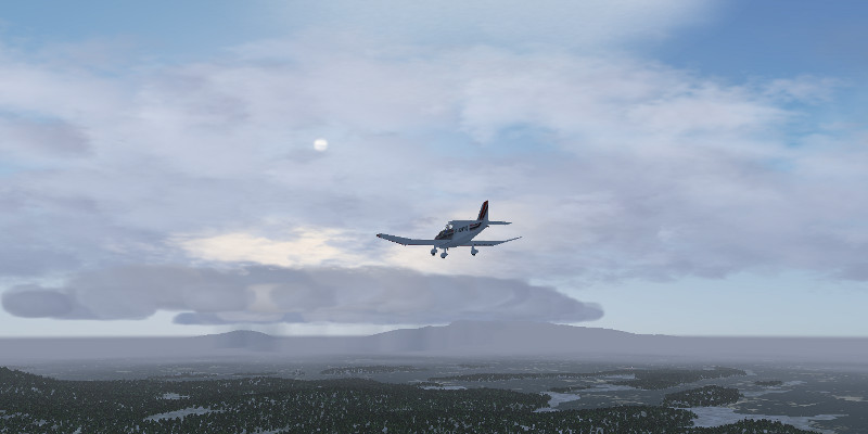
Precipitation is rendered beneath overdeveloping Congestus and Cumulonimbus clouds as well as beneath layered clouds. Either via a METAR string or on the advanced options configuration tab, the outside temperature can be specified – and precipitation changes from rain into snow accordingly. Also on the configuration tab, the stability of the convective air layer can be determined. Try combining an unstable convective layer with stronger winds, and watch turbulence evolve and rugged clouds with strong vertical development appear, or select a very stable atmosphere and observe well-shaped, large Cumulus clouds evolve. Or try the thunderstorm scenario, and observe large Cumulonimbus clouds tower over the scene.

Using Environment shader effects, it is possible to add a snowline, wet terrain with gleaming puddles or drift ice into the scene – use this for best effect in rainy or snowy weather.

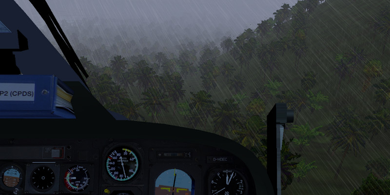
Try setting up a stormy scenario by adjusting the wind, and watch trees sway in the wind. Can you fly a helicopter in 30 kt winds and torrential rainfall?


Lighting

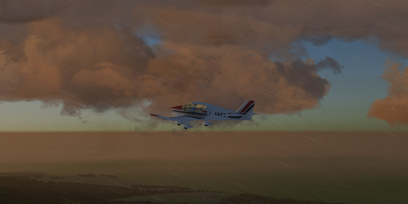
Advanced Weather is fully interfaced with the Atmospheric Light Scattering rendering framework – which means clouds in low light get differential lighting according to altitude: While cloud bottoms of Cumulonimbus clouds may already be in shadow, cloud tops can still receive light. With the sun behind them, faint clouds glow in bright radiance whereas thick clouds show shadows, making for a beautiful play of light and shade.

The weather configuration tab also contains an air pollution effect – use this to see low light colors of sky and clouds change from clean air to smog.

Try an early morning takeoff before dawn, or flying into the night, and watch the low light illuminating the scene – there’s nothing quite as nice as a sunrise in the mountains.


Advanced Weather for Flightgear – made for pilots who love to watch clouds! All features shown will be available for the next official release!

Fly Hawaii!

Author: Thorsten Renk

Destination Hawaii

One of the first places available as hires scenery in Flightgear, and also among the first places to receive a dedicated regional texture scheme, the island chain of Hawaii is a very spectacular destination in the Flightgear world. It offers a compelling variety of terrain from dry and barren lava plains to lush tropical rainforest, from the gentle fertile plains to rugged mountains and steep cliffs towering over the sea and from the densely populated island of Oahu to uninhabited Kaho’olawe.

Flying Hawaii can be easy or challenging – there are busy international airports and lone airstrips in remote locations, the altitude of the terrain ranges from sea level all the way up to Mauna Kea towering at 13,796 ft and steep gorges cut into the lava cliffs allow for tricky helicopter excursions.

Currently the scenery is only available via TerraSync and not by direct download from the website, presumably this will change with the next release of world scenery. While the release preparations for Flightgear 2.10 are underway, this article provides a first glimpse into some stunning new features which are currently being developed for the 3.0 release in summer 2013 – high resolution terrain texturing for closeup scenes.

Aeronautical charts for the whole of Hawaii are available online at skyvector.com, see for instance here for all charts relevant for Honolulu International Airport.

Hawaii ‘Big Island’

With a total area of 4,028 square miles, Hawaii is by far the biggest island of the archipelago, exceeding the size of all other islands taken together. It is also the youngest of all islands, dominated by the gentle rising cones of the five massive shield volcanoes Kohala, Mauna Kea, Hualalai, Mauna Loa and Kilauea, with the last two still being active.

The central part of the island is occupied by the twin cones of Mauna Kea (foreground) and Mauna Loa (background) which both reach above 13,000 ft and consists of extended lava fields, while the coastal region is somewhat more fertile.

The first destination reached however when arriving from the Honolulu region is Upolu Point, a region of eroded volcanic rock and spectacular gorges.

A flight to Hilo, the main city of the island, can pass between the two major shield volcanoes and requires a climb from sea level to more than 7,000 ft, which requires some adjustment of the mixture in a single-engine propeller plane. The climb to the pass is mainly above arid grasslands.

At higher altitudes, the spectacular lava fields of Mauna Loa dominate the scene.

Here is yet another view on Mauna Kea from the pass – often the volcanoes reach above the cloud layer.

Seen from the pass, Hilo seems close, but the slope of the terrain is so gentle that it is very easy to underestimate the true distance. Towards the coast, forests and fertile ground dominate the scene again.

Maui

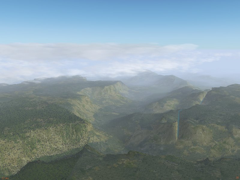
Maui is perhaps the island with the most diverse terrain. Its eastern part is dominated by the mighty cone of Haleakala, reaching just above 10,000 ft. The middle part is a fertile valley, whereas the western part features the rugged West Maui Mountains, which are considerably lower than Haleakala, but certainly make up for that with steep cliffs and deeply cut valleys.

Since the prevailing winds come from the northern side, air rises on the flanks of Haleakala, leading to fertile and overgrown northern slopes, whereas the southern slopes of Haleakala look completely different and show rather different weather.

Flightgear’s Advanced Weather is actually capable of simulating the resulting distribution of clouds from this effect – in fact, Haleakala has been an inportant test case in the development of the weather system.

Closely grouped in the vicinity of Maui are also the islands Lanai, Molokai and Kaho’olawe, easy to see in clear weather, thus Maui is an ideal starting point for island-hopping adventures.

Approaching from east, the scenery is dominated by Haleakala, here the more arid southern slopes are seen.

Maui is substantially older than Hawaii island, and so the volcano has started to erode quite significantly when compared to Mauna Loa – as a result, the fertile land extends much higher up. Haleakala crater however remains a rather impressive sight.

When approaching from the west, the cliffs and gorges of the West Maui Mountains are the first feature to become apparent.

On a clear day, the surrounding islands (here Molokai in the background) can clearly be seen:

The West Maui Mountains themselves contain quite some impressive sights – it is especially worthwhile to explore the various canyons and cliffs with a helicopter.

Yet another flyby view from the F-14b RIO position on the West Maui Mountains:

Oahu

Going west, the geological age of the island chain increases, and thus terrain features become more gentle as the volcanic rock erodes and changes into fertile soil. The island of Oahu is where the majority of the Hawaiian population lives and where the capital Honolulu is located. This is also where Honolulu International Airport, the most busy of all Hawaiian airports is found, and the home of famous sights as Pearl Harbour. Honolulu was envisioned as an emergency landing site for the space shuttle, and in fact the ‘reef runway’ (shared, as the rest of the airfield, with Hickam Air Force Base) used to be designated for this purpose.

Oahu stretches between two mountain ridges, which rise up to an elevation of just over 4000 ft. Here is a view of the island from the west.

Central Oahu is flat and largely in agricultural use. In the background, Honolulu and Pearl Harbour can be seen.

One of the most scenic spots on the island is Kailua beach on the north-eastern coast, offering a spectacular constrast of steep cliffs, long beaches and lush tropical vegetation.

The hires ground texturing scheme for Oahu has been carefully designed to display the contrast between lush vegetation and the red volcanic soil.

The other islands – Lanai, Molokai, Kauai, Kaho’Olawe and Niihau

Lanai is a fairly arid and sparsely populated island south-west of Maui with a single airport. It is dominated by a single mountain ridge reaching just above 3000 ft, with some valleys carved by erosion.

Molokai is, like Maui, a fairly diverse island – its eastern part consists of steep and towering cliffs whereas its western part is mostly flat and gentle landscape. Kalaupapa airport (PHLU) is built on a peninsula just beneath the cliff faces.

Kaho’Olawe is a small, uninhabited island. It has no airport and can only be reached by helicopter.

Its surface is mostly composed of arid stretches and lava fields.

Kauai, the garden island, is one of the nicest bits of scenery in the Hawaiian islands. It features the spectacular Na’Pali coast and Waimea Canyon.

Sadly, the scenery in Flightgear is currently a bit of a let-down – the terrain shows some errors in Kauai, and neither the Na’Pali coast nor Waimea come anywhere close to the originals.

Here is a scene close to Hanalei:

Finally, the island of Niihau is not part of the high resolution scenery package, and thus not really worth visiting.

Some Hawaiian airports

Hilo International Airport (PHTO) is located on the eastern side of Hawaii island at the coast – in a vert scenic location close to the town of Hilo. It is one of the two major airports of the archipelago and with a runway length of 9,800 ft large enough to admit essentially all airplanes.

Kona International Airport (PHKO) is located in the lava fields at the western coast of Hawaii island. Three million pounds of dynamite have been used to flatten the lava flow on which it was constructed. It offers a single 11,000 ft runway which is second in length only to Honolulu International Airport.

Waimea-Kohala Airport (PHMU) is a not very busy public airfield at 2,600 ft altitude in the western drylands of Hawaii island. It offers a single 5,197 ft runway.

Princeville: (HI01) is a small private airport close to Hanalei on the garden island Kauai. It is only suitable for smaller aircraft.

Lihue: (PHLI) is the main airport of Kauai. It has mainly connections to Honolulu, but also some long-distance traffic to the US mainland.

12 Days of Flight Tips (Season 2)

Last year, Oscar (youtube user: osjcag) created a series of short “howto” movies called the 12 Days of FlightGear Tips.  This year he is producing Season #2!  Each day he releases a new tip in honor of the twelve days of Christmas. Make sure you check back each day for the new tip!  Even “seasoned” FlightGear pilots may pick up a new trick or two.  Enjoy!

[youtube]http://www.youtube.com/watch?v=zoLuf3wfrEs[/youtube]

[youtube]http://www.youtube.com/watch?v=zMvGkJfoBVo[/youtube]

[youtube]http://www.youtube.com/watch?v=-AuEqnpnT0Q[/youtube]

[youtube]http://www.youtube.com/watch?v=6sSiSz2z9q8[/youtube]

[youtube]http://www.youtube.com/watch?v=VRYDHpjiTrM[/youtube]

[youtube]http://www.youtube.com/watch?v=GbfauLTlW90[/youtube]

[youtube]http://www.youtube.com/watch?v=Szoyj2AniJQ[/youtube]

[youtube]http://www.youtube.com/watch?v=5jahhoLY9sQ[/youtube]

[youtube]http://www.youtube.com/watch?v=1aY3m9s10s4[/youtube]

[youtube]http://www.youtube.com/watch?v=AKsP-IgyYwY[/youtube]

[youtube]http://www.youtube.com/watch?v=W3kaBY0CFQA[/youtube]

[youtube]http://www.youtube.com/watch?v=m1u9mnWv3Cs[/youtube]

Terrain Texturing

Author: Thorsten Renk

Regional and procedural texturing

It’s perhaps not a big secret that the default Flightgear World Scenery does not look stunning everywhere in the world. Yet, with regional texturing in Flightgear 2.8 and easy to configure procedural texturing in the current development version 2.9, two techniques have arrived which have the potential to rapidly change this. But precisely what are these techniques?

Short of addons such as fgphotoscenery, Flightgear has never used aerial photographs for texturing. Instead, the terrain is described in terms of landclasses, and each landclass has an associated texture. Up to 2.8, these texture definitions were the same all over the world, Yet in reality, this is not true – cities in the US for instance tend to be organized in rectangular grid patterns which are completely uncommon in Europe, Irrigated crops in Asia are most likely rice terraces, whereas rice terraces are not a common sight in the US Mid-West. Regional texturing allows to define texturing schemes for specified geographical regions and allow to overcome these problems – European cities can now defined to look different from US cities.

Procedural texturing is an even more powerful technique. In the default rendering scheme, the terrain of a certain landclass is painted with a pre-defined texture, then the light is computed and this is what we see on the screen. Procedural texturing does not use a pre-defined texture, but computes the texture as part of the rendering process. This powerful technique allows textures to be sensitive to the environment and hence simulate wet or dusty terrain, to create the actual texture as a mixure of various overlay textures which change dependent on how steep the terrain is or to add snow cover with any density on the fly. Procedural texturing has been part of the shader effects in Flightgear 2.8, for instance in terms of the wind-dependent wave patterns of water, or the snowline settings, but in 2.9 it gained many additional options and most important is configurable without any knowledge of OpenGL rendering by just a few lines of xml code.

Procedural texturing is best illustrated pictorially – here is a scene (China Lake Naval Air Weapons Station (KNID), California) in default texturing. The visible terrain is mostly shrubland, and there is a pronounced tiling effect – the texture pattern is seen to repeat in the scene, leading to regular structures which become even more prominent from higher altitude.

The same scene in procedural texturing looks much more appealing – the random mixture of different base texture removes the tiling for good, and a thin dust effect creates the impression of dry terrain as appropriate for the near-desert location.

Unfortunately, procedural texturing does not come for free – computing textures on the fly creates a significant drain on framerate, thus procedural texturing is only suitable for modern graphics cards.

The structure of Flightgear Scenery

The combination of regional and procedural texturing is extremely powerful and allows to make dramatic improvements to the world scenery at the simple expense of few lines of xml code. Let’s look at an example location:

Canaima National Park in Venezuela is one of the world’s most fascinating mountain regions with table-mountains like Auyantepui towering over jungle terrain, featuring the world’s tallest waterfall, Angel Falls (3,287 ft). The scenery offers steep near-vertical cliffs hundreds of meters high, rugged and inaccessible plateaus atop the table mountains and lush tropical forest with winding reivers at their feet. The best place to access the park is Canaima airport (SVCN).

Yet, in the Flightgear default rendering scheme, Auyantepui is shown like this:

There is… something wrong here. In order to understand what goes wrong, let’s take a short look at the structure of the Flightgear scenery.

The basic ingredient of the scenery is the terrain mesh, containing the elevation data for all mesh points and the information what landclass the terrain between grid points is. The terrain mesh is created by a tool called TerraGear from public geodata. The output of this stage contains the altitude information of the terrain, and for instance the information that the terrain represents tropical forest (the so-called ‘landclass’).

Upon loading the terrain once it is used by Flightgear, the landclass is associated with a texture. At the same time, random objects such as buildings or trees are created and placed upon the terrain mesh where appropriate. Thus, the tropical forest landclass would at this step be associated with a forest texture and be populated with a large number of trees. At this stage, also shader effects are associated with a particular landclass, for instance water receives a reflection effect, whereas urban terrain may receive the urban shader effect.

In the last step, static (unique and shared) objects are added to the scene. These are objects which appear always at a given location, for instance airport terminals or special landmarks, and they are found in the Flightgear Scenery Database.

Armed with this knowledge, let’s analyze the above scene to find out what goes wrong: We can see that large parts of the table mountain get an agricultural texture. Visiting the scene with the ufo and using ctrl + alt + click (only in 2.9) on the offending terrain reveals that the mesh is here classified as ‘DryCrop’. This isn’t completely unreasonable, as the top of the table mountain is a rather barren grassland – but DryCrop becomes automatically associated with Europen-style agriculture textures – which look just plain silly in a place which in reality is utterly inaccessible, despite the valiant effort of the shader effect to change the agriculture to brown earth on steep slopes. Similarly, the nearby tropical forest is classified as ‘EvergreenForest’ (which is technically correct) – but EvergreenForest is associated with needle forest textures and needle trees.

Editing scenery texturing

There are various possibilities how this could be addressed. For instance, using TerraGear the landclasses in the scenery could be changed to something closer to reality. But to do this requires some learning, TerraGear is not a trivial tool. In this case, it is also unnecessary: The basic elevation mesh is in good order, the landclasses are not unreasonable, just the way textures and random objects are assigned to them is not working, and thus we need to change this.

The mapping of landclasses to textures and various other properties is controlled by a file called materials.xml. The regionalized version of it is found under $FGRoot/Materials/regions/materials.xml. In this file, for each landclass, a block of definitions exists. The idea is then to just copy the block for ‘DryCrop’ and edit the copy to contain an alternative definition valid for a particular geographical region, then change the texture to something more suitable. Plenty of nice textures already are in $FGRoot/Textures/Terrain/ and $FGRoot/Textures.high/Terrain/, so usually we don’t even need a new texture. While we’re at it, we might as well add two more lines to the etxture declaration specifying the overlay texture for procedural texturing. And that’s all it takes – next is EvergreenForest – we repeat the procedure and in addition change the tree texture from evergreen needle trees to tropical trees.

After just about an hour of editing materials.xml (the whole procedure is described in detail here), Canaima National Park looks like this:

Much better – isn’t it? Now all that’s missing is Angel Falls – we’re going to need a static model for this. The Particle System of Flightgear is going to be our friend here…

Canaima Sightseeing

After adding the model of Angel Falls using the ufo, Canaima National Park is ready for a sightseeing Flight (Flightgear 2.9 users can already enjoy it like this!) – once the landclass assignment is okay, procedural texturing takes care of the rest:

Steep cliffs and sheer drops flying over Auyantepui enroute to Angel Falls:

Table mountain tops reaching above the clouds:

Angel Falls seen from high altitude:

The barren top plateau of Auyantepui:

Tropical rainforest on return to Canaima airport:

Don’t wait for someone else to fix the terrain you want to explore – it’s easy, the tools are there and in many cases it’s more work to create a single model of a building than to make terrain texturing in a vast region look good!

Vertical takeoff and landing

The Harrier in Flightgear

Author: Thorsten Renk

The VTOL concept

Quite early on in the history of jet fighter aircraft, it was realized that a main vulnerability of jets is their reliance on an airbase and a runway, targets which can comparatively easily be taken out or temporarily disabled in a war, especially as the operational range of most fighters is quite limited and hence the base has to be relatively close to the front. Vertical takeoff and landing (VTOL) ability was seen as a way to overcome this problem in the 1950s, since a VTOL fighter could operate from basically anywhere.

The problem of designing a VTOL aircraft is however obvious – such an aircraft needs a thrust to weight ratio above one to lift from the ground with thrust vector pointed downward during takeoff and pointed backward during normal flight. Early designs involved planes landing on their tail (such as the Lockheed XFV-1 or the Ryan X-13 Vertijet), but these planes were difficult to control. Other designs experimented with auxiliary, downward-pointed engines, but their extra weight was found to be impractical in a fighter jet. For a long time the only truly successful design was the Harrier family achieving VTOL due to thrust vectoring nozzles. The Lockheed Martin F-35B is expected to continue the concept of a VTOL fighter in the next millenium.

In the Harrier, the jet exhaust passes through four vectoring nozzles surrounding the center of gravity of the plane. These nozzles can be vectored from zero degrees (to the rear) up to 98 degrees (down and slightly forward for deceleration in hover flight). Since there is no airstream in hover flight across any of the control surfaces, the plane is equipped with a reaction control system with a set of extra small thrusters.

All in all, the VTOL ability comes at a price – engine maintenance is difficult (the wings have to come off), the plane is difficult to fly and pilots have described it as ‘unforgiving’ and the accident rate has been comparatively high. Nevertheless, the Harrier has been considered a successful fighter design.

Vertical takeoff

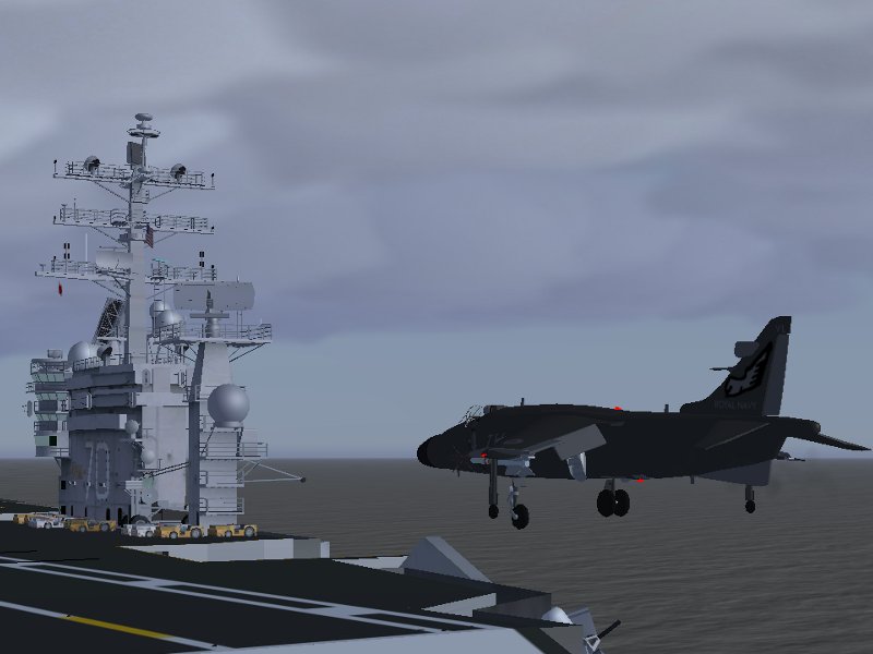
Let’s explore the Harrier in Flightgear! For any VTOL design, weight is a critical consideration. The plane will lift only if the thrust-to-weight ratio is above one, thus with a full fuel and weapons load, the plane is too heavy to lift. For this reason, whenever feasible, the plane is actually used in STOL (short takeoff and landing) mode with thrust only partially vectored down and lift provided partially by aerodynamical lift and partially by downward thrust. In this case, we’d like to do a VTOL takeoff though. With full fuel loadout and two AIM-9L missiles, the plane is still able to lift from the deck of USS Carl Vinson.

After doing my preflight checks, I vector the thrust about 83 degrees down (the Harrier sits on the gear with the nose pointed up, so if I vector 90 degrees down the plane moves backward on takeoff, which is very dangerous). After releasing the parking brakes, the thrust is slowly increased and the thrust vector corrected such that the plane doesn’t move – now thrust points exactly down. I then increase the thrust until the plane lifts from the deck (this means almost full throttle for the takeoff load), and then, a few meters above the ground vector the thrust very slightly backward to accelerate.

The Harrier has a tendency to lift the nose at this point, so I am very careful to push the nose down early on. As the plane accelerates, I vector the thrust more and more back and retract the gear, and within a few seconds the plane accelerates to above 100 kt and less and less downward thrust is needed. At around 240 kt, I vector the thrust completely back and the Harrier reacts like a normal fighter jet.

The Harrier in flight

It is important to remember to reduce thrust at this point – the Harrier has a very powerful engine due to the need to lift, but it is also a very fuel-consuming engine, and in horizontal flight with full thrust it won’t go anywhere before the tanks are empty.

Once in the air, the Harrier is a fairly typical older-generation fighter jet – it has a high roll rate, a fairly small turn radius and can climb quickly to high altitude. Lacking an afterburner, it is (despite the powerful engine) not a supersonic plane. Also, without thrust vectoring the plane doesn’t handle too well at slow airspeeds and cannot compete with swept-wing designs like the F-14b. However, thrust vectoring can be used in maneuvering to suddenly decelerate the plane by vectoring the thrust forward or to achieve a very tight turn radius.

The Harrier can also land like a conventional fighter jet, in this case vectoring the thrust about 45 degrees down acts like extra flaps – the plane slows down as the backward thrust is reduced and gets extra lift from the downward thrust component.

The current cockpit of the Flightgear Harrier could clearly use some attention, it has rather basic texturing, not all instruments are implemented and all in all it tends to be the least realistic visual element in the scene.

In flight planning, it is important to remember that unlike a conventional landing, a vertical landing involves a prolonged period of full thrust, and thus (especially during practice of the VTOL approach) about 20 to 25%% of the total fuel load should be available for the landing.

Not a helicopter

Despite some similarities to helicopter flight, it should be remembered that the Harrier is not a helicopter and reacts somewhat differently. First of all, torque generated by the main rotor is a big issue for helicopters and needs to be compensated for, but torque is absent for a jet engine – the Harrier does not in itself develop a tendency to yaw when lifting off the ground.

However, the roll stability is dramatically different in hover flight. One can think of a helicopter as the mass of the helicopter body hanging underneath the lifting rotor. Thus, when the body of the helicopter starts to roll, it has a tendency to swing like a pendulum underneath the rotor, but the roll doesn’t grow by itself. In contrast, the Harrier is a mass balanced upon a column of lifting thrust, so any roll tendency will not lead to a pendulum motion but will be self-reinforcing, and if it is not corrected will lead to an unstable condition.

An unstable situation however is worse in the Harrier than in a helicopter since a helicopter pilot has more options – since a helicopter pilot can use the cyclic control to tilt the rotor to the side and well as forward/backward (and so also fly the helicopter sideways or backward). The Harrier can vector thrust only backward or down, but not to the side, i.e. it can not easily be flown sideways and has limited control over unstable situations.

Finally, on a more prosaic note, the view down is much worse in the Harrier than in many helicopter cockpits. For all these reasons, it is safer to land with a small forward velocity (which can quickly be reduced on the ground) than to touch down actually without any forward velocity.

Vertical landing

I fly pretty much a conventional approach till about 10 miles distance to the carrier. At this point I reduce the airspeed to 250 kt and start to get flaps out. I put throttle to idle and vector the nozzles down to 90 degrees. As the plane slows down due to drag, about below 200 kt the aerodynamical lift reduces significantly and I keep increasing throttle to compensate. Below 150 kt, I extend the gear. As the carrier gets closer, I aim to reduce the airspeed to about 50 kt – since the Carrier moves with about 15 kt, that gives me some 35 kt relative motion to the carrier, enough to keep the approach stable. I vector thrust slightly forward and backward from the 90 degree position to adjust airspeed and monitor throttle to control my descent rate.

At 50 kt airspeed, there is no significant aerodynamical lift left, so the plane hovers under almost full thust slowly towards the carrier. It is important to monitor both airspeed and descent rate at this point – if the airspeed drops too much, the reduction of the small remaining lift component means that I descend too fast and get below the flight deck. In addition, in this stage of the approach wind gusts are felt quite badly and can ruin the whole approach if the plane does not have enough forward motion.

Compared to a carrier landing in the F-14b, it feels as if the Harrier approaches the flight deck centimeter by centimeter, although at this point there are about 20 kt relative motion. I keep the nose of the Harrier level with the horizon and pull it up to 8 degrees only after I am above the flightdeck – this effectively vectors thrust forward and kills my remaining airspeed, this in turn reduces lift and combined with a slight decrease in throttle lets me touch down with a forward motion of less than 10 kt, which I kill by applying brakes while I push the throttle quickly to idle to let the plane settle down firmly and avoid being thrown by a sudden gust.

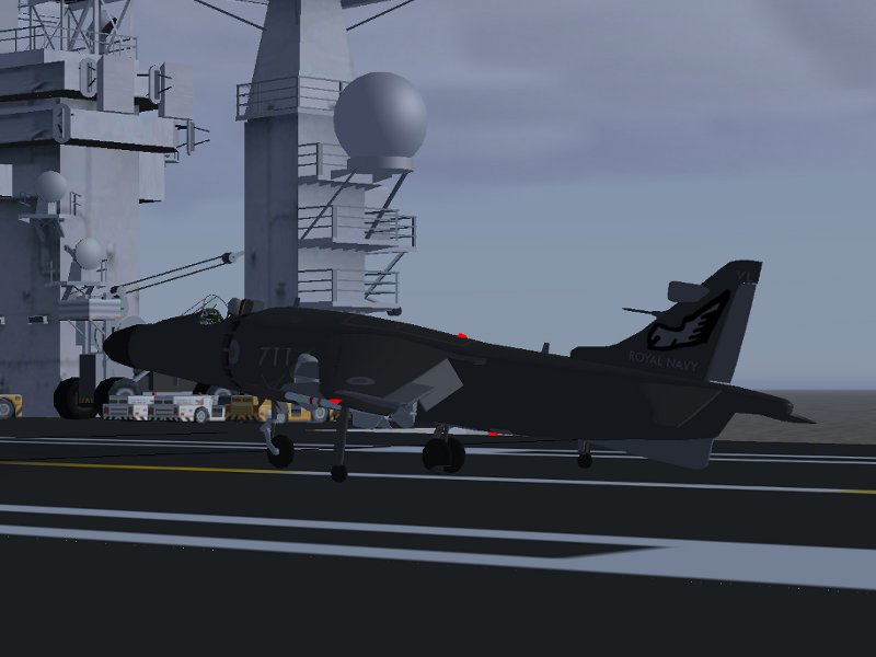
As can be seen here, the Harrier rests in a slightly unusual configuration with the nose pointing upward.

Clearly, the Harrier is not one of the most detailed aircraft available in Flightgear. However, it provides a good, solid hands-on understanding of the advantages and problems of the VTOL concept. Other versions of the Harrier can be found in the Flightgear UK hangar. The above screenshots have been made with the development version of Flightgear using lightfield shading and the environment-sensitive detailed water shader.

Mountain-flying in the French Alps

Author: Thorsten Renk

Altiports

If you are up for some challenging approaches and tricky landings while you like to enjoy spectacular scenery, here is a good suggestion for a destination – try visiting the French altiports.

Altiports are small airfields for small aircraft and helicopters located high up in the mountains, often serving a ski resort. The runway is usually short and quite steeply sloped (in the case of Courchevel, the slope is a solid 18.5%), and all landings are done uphill with no go-around procedure. Since the alitports are by no means in the mountain summit region, the approaches must be done in the confined regions of a valley, which means they are usually curved and somewhat dangerous. As a rule, no navaids are available, thus altiports can only operate in good weather – all this adds up to a challenge. In fact, the History Channel program ‘Most Extreme Airports’ ranks Courchevel as the 7th most dangerous airport in the world, and once you do your first approach, you will quickly discover why.

Flying the French Alps is significantly more interesting by using the highly detailed custom scenery which is available for free under a Creative Commons Attribution-ShareAlike 3.0 here. There are six altiports in the French Alps, L’Alpe d’Huez, Courchevel, La Rosiére, Mégève, Méribel and Valloire, along with a number of airfields in the valleys. The first two of these, L’Alpe d’Huez (LFHU) and Courchevel (LFLJ), have been modelled in detail for the custom scenery and are available from the PAF team hangar here. This package also contains a detailed model of Grenoble Le Versoud Aerodrome (LFLG) which is a good place to take off for a first look at Courchevel or L’Alpe d’Huez.

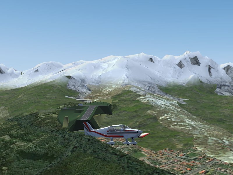
Here is a picture of the layout of L’Alpe d’Huez as it appears in Flightgear:

The challenges of mountain-flying

Beginners are probably better off with a powerful turboprop STOL aircraft like the de Havilland DHC-6 ‘Twin Otter’ which has the climb rate to pull out of dangerous situations, but the real challenge is better experienced in a small aircraft like the Robin DR-400. With a constant pitch single propeller and no retractable gear, this plane is, especially when passengers and baggage are on board, seriously taxed to climb over the high mountain ridges which in many cases reach above 11.000 ft.

The fuel and payload menu item allows to adjust both the fuel level in the tanks as well as any additional weight on board. Asymmetric weight distribution in JSBSim is in fact taken into account properly, if for instance the copilot weight is reduced in flight, the plane starts to roll.

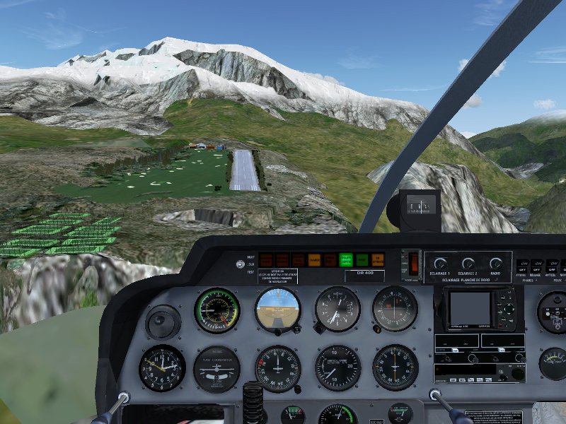
Here, a DR-400 is lined up for takeoff in Courchevel with L’Alpe d’Huez as destimation. Since the airport is at an altitude of about 6500 ft, it is important to adjust the mixture properly to the altitude in order to get the full engine power for takeoff.

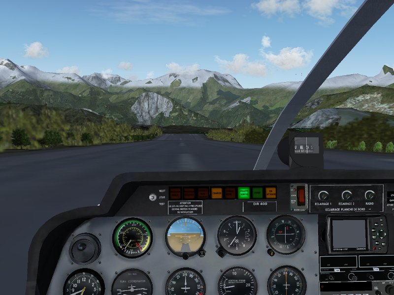
Once the engine is running at full power, the brakes are released and the plane accelerates quickly down the steeply sloped runway, becoming airborn halfway. Departing from Courchevel, it becomes readily apparent why the altiport is challenging and why there is no go-around procedure available.

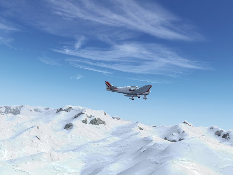
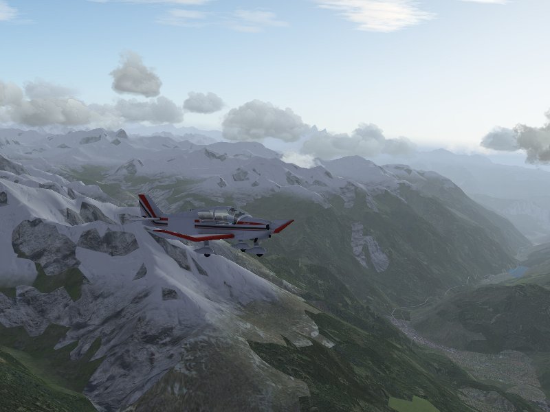
On the direct way, the high ridges of the Vanoise National Park with elevations well above 9000 ft have to be crossed – with the fully loaded DR-400, this is a slow climb over snow-covered mountains.

Snowcover in Flightgear can be generated by shader effects with a user-controlled snowline. Since the shader effect does not place snow on steep slopes, the outcome looks very compelling.

However, also the lower valleys during the descent to L’Alpe d’Huez have a lot to offer.

This is the final approach, aiming between rocky cliffs. At this point there is still a chance to break off.

The final moments – we are committed to a landing now. The trick is to aim low and reach the threshold in level flight, then pull up to follow the slope of the runway, let gravity develerate the plane and let it touch down softly (if you try a normal approach on a runway with such a steep slope, you will break the gear) and not throttle back engine too fast, because the plane still needs to reach the top of the runway, and once the plane comes to a halt on the slope, the engine often is not powerful enough to get it moving again.

All went well – time to enjoy the company of the other pilots and have a coffee before heading back to Courchevel.

In bad weather, things can be much worse. If the valley is cloud-filled, there is no choice but to turn back if no good view of the airport is possible early on. And in gusty crosswinds, hitting the runway just right is a challenge on its own.

The beauty of mountain flying

However, once one masters the challenges of high-altitude flight and navigating in the confines of valleys, flying the Franch Alps in nice weather is primarily a good way to see spectacular scenery. Let’s head back to Courchevel!

Here, the DR-400 accelerates down the sloped runway of L’Alpe d’Huez – going down, airplanes accelerate much faster than one is used to on level runways, so we can get airborn in just a few moments.

Leaving L’Alpe d’Huez, the village and ski resort becomes visible. The winding road up from the valley is actually a popular mountain stage of the Tour de France.

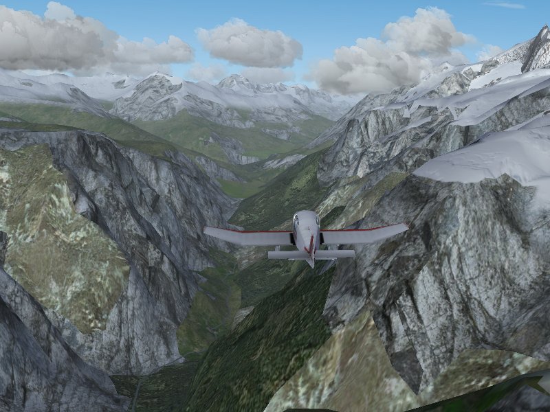
The vicinity of L’Alpe d’Huez has deep valleys, spectacular cliffs and Canyons and steep, rocky mountain faces – one can fly through the valleys or high above the mountain ridges.

Enroute to Courchevel, we leave the high ridges behind and cross to the Vanoise Park in the vicinity of Modane.

Descending again, Courchevel becomes visible (just to the left of the screenshot) while the lower valleys vanish in afternoon fog.

Final impressions

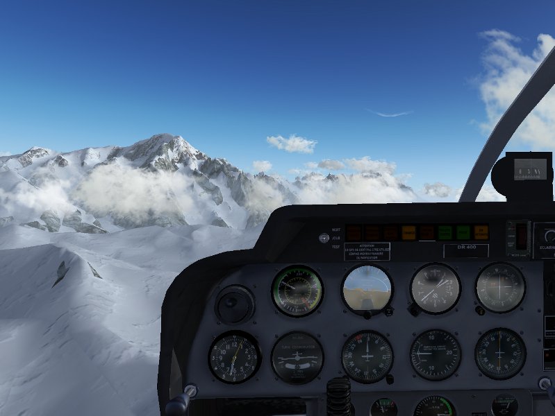
Of course, one of the must-see destinations in the vicintiy is Mt. Blanc, towering at 15.781 ft above most cloud development. Its rocky lower slopes and steep cliffs make for some really spectacular scenery, and especially at sunrise or sunset, the view from the summit is spectacular.

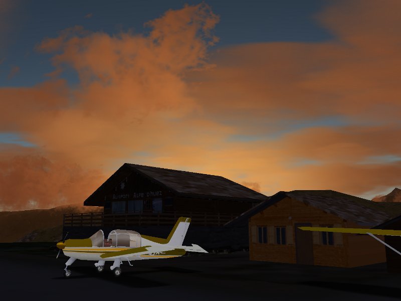
As the sun goes down, the last clouds light up over L’Alpe d’Huez which is to be closed over the night. High time to get back to Grenoble.

Developing Computer Vision Algorithms with FlightGear

Ocean Debris

On March 12, 2012 suspected Japanese tsunami debris was discovered washed up on the beaches of Long Beach, CA.  On March 11 a deserted fishing vessel was spotted off the coast of British Columbia; by March 24 it had drifted within 120 miles of the coastline.  For many years NOAA.gov has been monitoring an every growing area in the North Pacific dubbed the “Great Pacific Garbage Patch” that appears to be collecting and concentrating all manner of plastic debris from all over the world.  Whether you are a dedicated environmentalist, or a person that leans more towards managing and sustaining the Earth’s valuable resources indefinitely, or are simply annoyed at having to photoshop garbage out of your pristine vacation pictures; the rapidly increasing amounts of trapped ocean debris should be a concern for everyone.  How does any of this relate to the FlightGear simulator?  Please read on!


What is “Computer Vision?”

Computer vision is a broad field that involves processing real world images or video to try to automatically extract data or intelligence.  Applications range from identifying items or features of interest (such as facial recognition) to extracting geometry and physically locating or reconstructing the layout of a scene to manipulating images in clever or useful ways.  In many ways computer vision is a fascinating and magical   area.  We all have seen software programs that can identify every picture of our Aunt Tina on our computer after we’ve identified her face in one or two pictures.  There are computer vision systems that can track people or objects that move through a network of many camera views; computer vision systems can estimate your head orientation and even figure out what direction you are looking or what object you are looking at..  Computer vision software can recognize cars, read printed text, and scan for subtle features hidden in images — and because these programs are automated, they can run around the clock and process vast amounts of imagery.  They never get fatigued, they never get bored, and they never start day dreaming about their weekend plans.

Developing a Computer Vision Application

Writing an application to do computer vision is similar to writing any other application.  The basic cycle of edit, compile, test, repeat exists like with any other program.  Computer vision algorithms apply logical rules and procedures to the image data in consistent ways to accomplish their tasks.  There really isn’t any magic, even though the results do seem magical when they outperform the abilities or pace of a human.  However, it can be a challenge to develop some computer vision applications if you do not have good access to the kind of imagery you plan to ultimately be processing.

As you can imagine, computer vision applications must deal with huge volumes of data.  Often they process live video data from multiple cameras and that data may need to be associated with other data sources in real time — something that may not be possible to test in a lab with prerecorded video.

Imagine you are developing an application which will process aerial imagery to extract some data (i.e. facial recognition) or locate and track items of interest (i.e. a big chunk of debris in the ocean.)  It could very likely be the case that you do not have much sample video to test with.  In the case of ocean debrid, it may be that you do have video from the correct altitude or taken at the correct air speed, or with the correct camera field of view or camera angle.  However, computer programs are most efficiently developed in the lab with repeatable test data and not in the field with whatever random imagery the day offers — this can lead to a disconnect between what imagery is needed for effective testing and what imagery is available.

Hunting and Tracking Ocean Debris


For several years I have been involved with a company that develops UAV’s and remote sensing and tracking systems for marine survey and research use.  One of our primary partners is NOAA.gov.  NOAA has a keen interest in understanding, tracking, and ultimately cleaning up debris in the ocean.  With the Japanese Tsunami last year, the issue of debris accumulating in our oceans has become even more important and critical, yet there is no effective strategy available for locating and removing debris from the ocean.

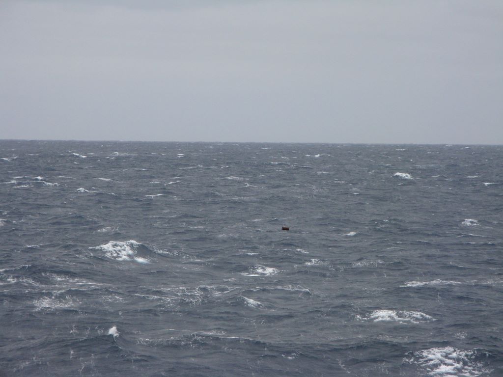
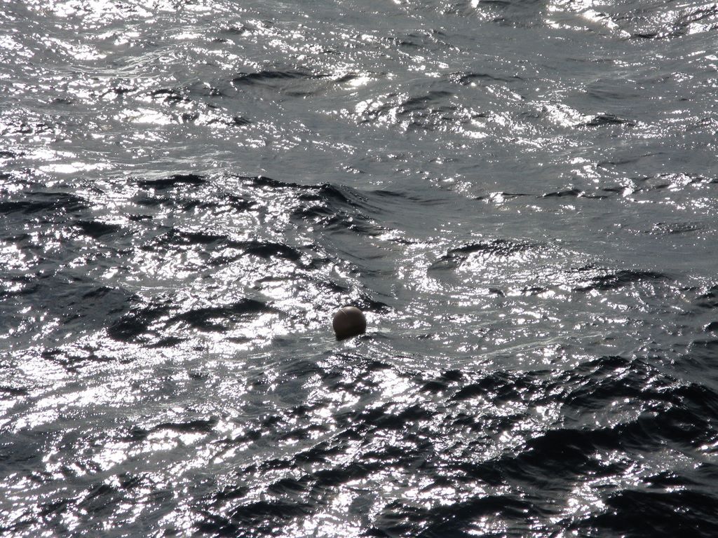
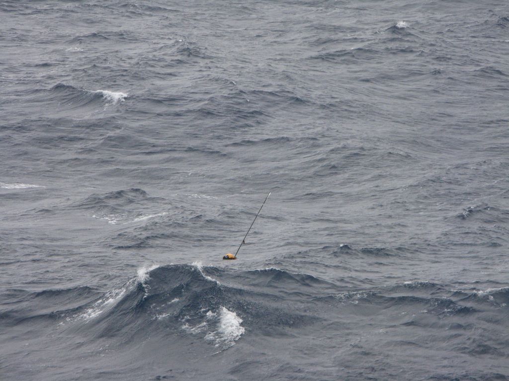
A satellite can survey huge areas, but not at the detail to identify specific pieces of debris.  A manned aircraft can fly at several hundred kts and cover a wide area at a low enough altitude to spot individual pieces of debris, but there is nothing you can do when debris is located.  A ship travels very slowly and has a very narrow range of view for onboard spotters.  A ship might do 10 kts (give or take) and with binoculars a human might be able to spot debris one or two miles away — if they are looking in the right direction at the exact moment a swell lifts the debris up into view in front of the nearer swells.  The upper decks of a ship offer some height for observing debris, but swells hide objects more than they reveal them.   You have to be looking in the right direction at the right time to even have a chance to spot something.  In addition to all the other challenges of ship-board debris spotting, the rolling/pitching motion of the ship makes the use of binoculars very difficult and very fatiguing.

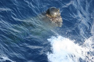
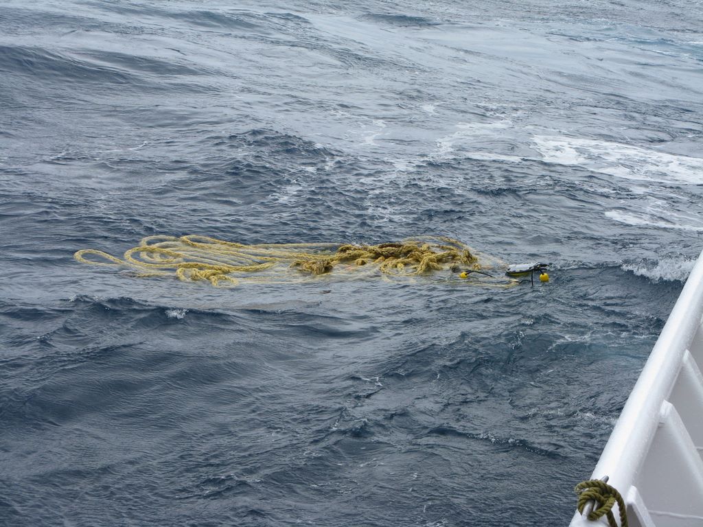
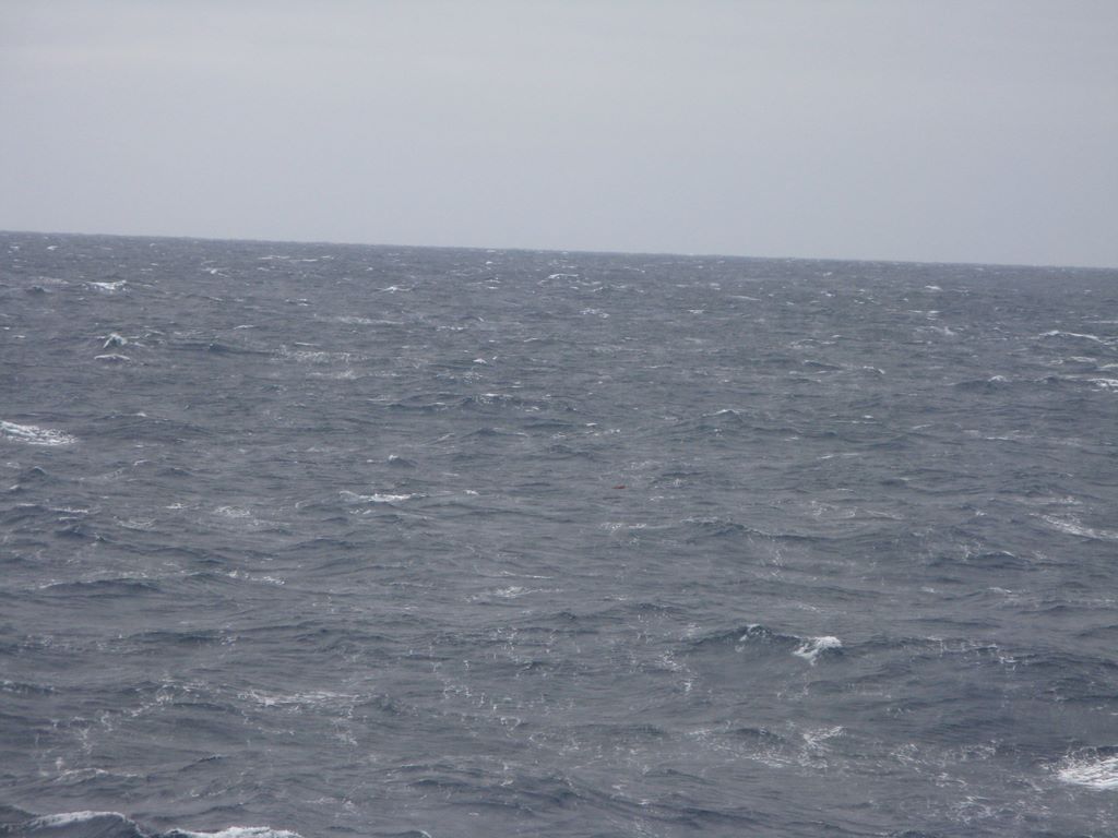
The following two pictures were taken seconds apart.  Can you spot the debris in the first image?  In the second? (You can click on them to see the full size version.)


A UAS offers numerous advantages over a human operator searching from the highest deck of a ship.  The UAS offers a much higher altitude perspective looking downward so that swells and waves can’t hide objects.  The UAS offers faster speeds to visually cover more area in the same amount of time.  The UAS can carry a variety of image sensors including IR cameras or multi-spectral cameras which offer increased ability to reliably detect certain types of objects under a variety of conditions.  Add computer vision software to process the UAV’s imagery and an effective debris location and tracking system begins to emerge.

The UAS has limited range though; and if a significant object is detected, it has no ability to tag or recover the object.  Thus it is important to combine UAV operations with a ship in the vicinity to support those UAV operations and be able to take action when something is found.

Visual Challenges of Computer Vision in a Marine Environment


As with any computer vision application, narrowing the scope and focus of the application as much as possible makes solving the problem easier.  Using the example of a UAV flying over the ocean and collecting imagery from a camera looking straight down, then the camera frame will always be completely filled with a straight-down view of the ocean surface.  We assume we don’t have to deal with the horizon, sky, or clouds or nearby coastline.  The result is that the ocean for the most part is some shade of blue — that is convenient.  Anything that is not blue is not ocean and then becomes highly interesting.  But despite limiting the scope of the problem in this way, the computer vision application still has to deal with several significant challenges: 1. Sun glint — the sun reflecting back at us off the water.  2. Windy days in excess of 12-15 kts produces breaking waves, foam, and even streaking (lines of foam) on the water.  Visually, sun-glint and foam impair our ability to spot objects in the water.

Why use FlightGear instead of real camera imagery?

FlightGear generates realistic views of the earth and offers complete control over the altitude, speed, camera orientation, and field of view of a simulated flight.  In addition, FlightGear can provide flight telemetry data and other data that is useful for testing or simulating real world environments.  We can also control the time of day, clouds, wind, precipitation and fly missions anywhere we like.  With FlightGear’s scripting engine, it’s possible to stage static or dynamic scenarios to create the sort of test cases we expect to be able to ultimately handle.  Of course only a small slice of computer vision applications relate to processing aerial imagery, but as UAV’s begin to attract the attention of more and more civilian and private organizations, the need for automatically processing huge volumes of imagery data will only increase.

FlightGear “Synthic Imagery” vs. real world camera imagery


As FlightGear continues to develop and evolve, the quality and realism of it’s graphics also are improving.  In the most recent version we have taken significant strides forward in drawing realistic ocean scenes that include accurate coloring, accurate rendering of different sea states and types of waves, very realistic sun glint, realistic sea foam (the result of breaking waves on windy days), and even rolling wake and foam created by large ships.  The quality of FlightGear ocean scenes can now (in many cases) make them almost indistinguishable from real camera imagery.

What is OpenCV?

OpenCV is a library of data structures and functions that offers most basic image processing tasks, as well as many of the more common advanced functions.  OpenCV provides the building blocks a developer needs in order to start writing a computer vision application.  OpenCV runs on Linux, Windows, Mac, and even Android.

How to connect an image processing application to FlightGear in “real time”.

Disclaimer: the nuts and bolts that I explain in this section are focused on the Linux platform.  These same tools are likely available on other platforms and may be leveraged in the same (or similar) ways to accomplish the same thing — but outside Linux your mileage may vary as they say.

I know how to capture a portion of my desktop as a movie and save it to a file.  My computer vision application knows how to read a movie file and process it frame by frame.  What is missing is that I want to be able to do this in real time without having to fly and save the video and the process it later.  My basic strategy is to first create a unix file system “fifo”, then write the captured video to this fifo, and simultaneously read from the other end of the fifo into my computer vision application.

  1.  Start FlightGear at your simulated camera resolution.  I have a cheap web cam that does basic vga (640×480) video, so using that as my “standard” I can run: “fgfs –geometry=640×480” to launch flightgear with the correct window size.  Next I drag the FlightGear window into the upper left corner of my screen so it is in a known location.
  2. Make your fifo if it doesn’t already exist.  For instance: “mkfifo /tmp/ffmpeg-fifo.avi”
  3. Start up the computer vision application:  “my-vision-app –infile /tmp/ffmpeg-fifo.avi”
  4. Start up the ffmpeg desktop movie capture utility (I have a little script I setup so I don’t have to remember all these options every time):  “ffmpeg -f alsa -i default -f x11grab -s 640×480 -r 15 -b 200k -bf 2 -g 300 -i :0.0+1,58 -ar 22050 -ab 128k -acodec libmp3lame -vcodec mjpeg -sameq -y /tmp/ffmpeg-fifo.avi”

That’s all it takes and the computer vision application is up and processing live FlightGear generated imagery.  One thing I discovered with fifo’s.: it seems to work best to start the reader (the CV app) before starting the writer (ffmpeg).  This way the buffers don’t fill up and cause delays.

Results

Here is a snapshot of the anomaly detection and tracking in action:

The original image:

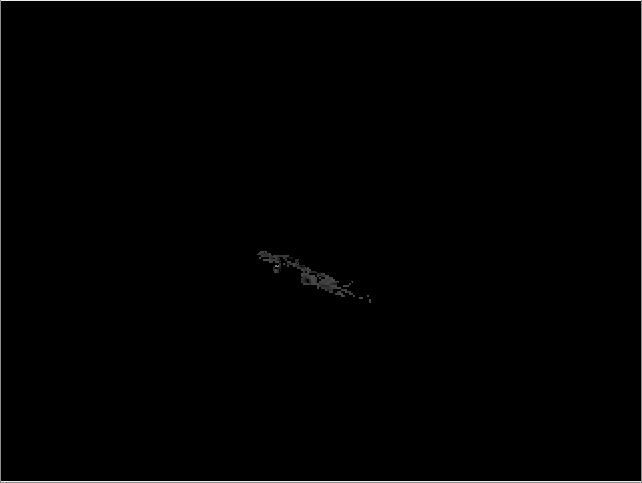
The image partitioned into water vs. not-water.

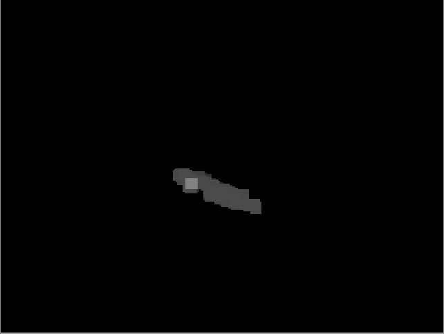
Dilating the mask (connects the noisy dots):

Eroding the dilated mask (to shink it back to approximately the original size and location in the image):

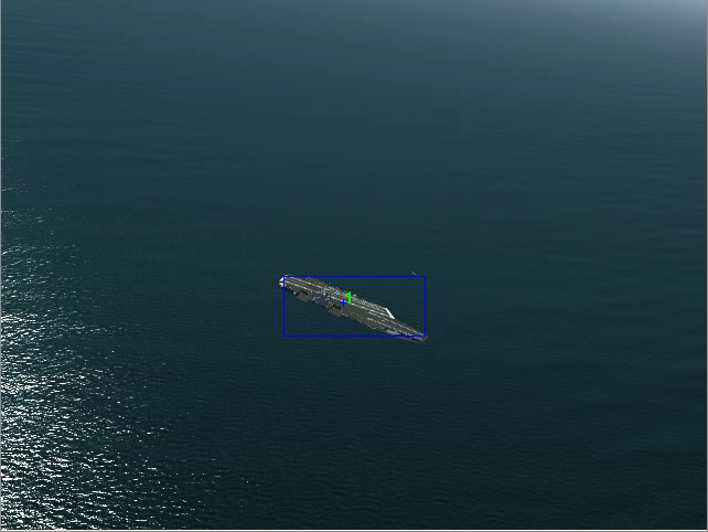
The final composite image showing the detected blob on top of the original frame:

Lastly, here is a youtube video showing all the pieces working together.  In FlightGear: I have created a random debris field scattered across an area of open  ocean about 6nm x  6nm.  I have added a downward looking camera to my test aircraft.  Then I built a route that flew several “transacts” (straight line paths) through the debris field.  I used the above mentioned procedure to feed the live FlightGear imagery into my computer vision algorithm that detects and tracks anomalies.  The debris you tend to see from the air looks very small — usually just a few pixels at best in your image, so the algorithm needs careful tuning to avoid false positives and missing objects.

[youtube]fDPY1PtnBtU[/youtube]

Please watch this video in full screen resolution so you can see the specks of debris and the tracking algorithm in action!